Toyota Camry (XV70): A25a-fks Oil And Oil Filter
Components
COMPONENTS
ILLUSTRATION
|
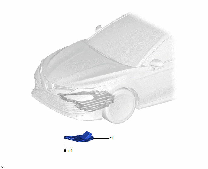
*1 | CENTER NO. 4 ENGINE UNDER COVER |
- | - |
ILLUSTRATION
|
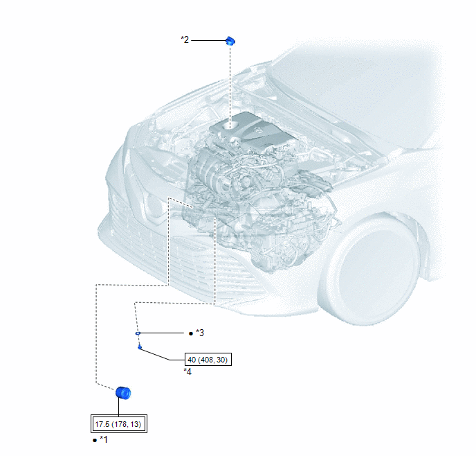
*1 | OIL FILTER SUB-ASSEMBLY |
*2 | OIL FILLER CAP SUB-ASSEMBLY |
|
*3 | GASKET |
*4 | OIL PAN DRAIN PLUG |
.png) |
Tightening torque for "Major areas involving basic vehicle performance such as moving/turning/stopping": N*m (kgf*cm, ft.*lbf) |
.png) |
N*m (kgf*cm, ft.*lbf): Specified torque |
|
● | Non-reusable part |
- | - |
Replacement
REPLACEMENT
CAUTION / NOTICE / HINT
CAUTION:
- Prolonged and repeated contact with engine oil will result in the removal of natural oils from the skin, leading to dryness, irritation and dermatitis. In addition, used engine oil contains potentially harmful contaminants which may cause skin cancer.
- Wear protective clothing and gloves. Avoid contact with used oil. If contact occurs, wash your skin thoroughly with soap or waterless hand cleaner. Never use gasoline, thinners, or solvents to wash the skin.
- In order to protect the environment, dispose of used oil and used oil filters at designated disposal sites only.
PROCEDURE
1. REMOVE CENTER NO. 4 ENGINE UNDER COVER
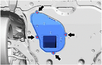
| (a) Remove the 4 screws and center No. 4 engine under cover. |
|
2. DRAIN ENGINE OIL
(a) Remove the oil filler cap sub-assembly.
(b) Remove the oil pan drain plug and gasket, and drain the engine oil into a container.
(c) Clean the oil pan drain plug.
(d) Install a new gasket to the oil pan drain plug.
(e) Install the oil pan drain plug.
Torque:
40 N
READ NEXT:
 Components
COMPONENTS ILLUSTRATION
*A for 2WD
*B for AWD
*1 IGNITION COIL ASSEMBLY
*2 NO. 1 ENGINE COVER SUB-ASSEMBLY
*3 SPARK PLUG
- -
N*m
Removal
REMOVAL CAUTION / NOTICE / HINT
The necessary procedures (adjustment, calibration, initialization, or registration) that must be performed after parts are removed and installed, or replaced during s
SEE MORE:
On-vehicle Inspection
ON-VEHICLE INSPECTION PROCEDURE
1. FUEL PUMP ASSEMBLY OPERATION (a) Check fuel pressure. (1) Connect the Techstream to the DLC3.
(2) Start the engine. (3) Turn the Techstream on. (4) Enter the following menus: Powertrain / Engine / Active Test / Control the Target Fuel Pressure Offset. Powertrai
Replacement
REPLACEMENT CAUTION / NOTICE / HINT
The necessary procedures (adjustment, calibration, initialization, or registration) that must be performed after parts are removed and installed, or replaced during automatic transaxle fluid replacement are shown below. Necessary Procedures After Parts Removed/I
