Toyota Camry (XV70): Adjustment
ADJUSTMENT
PROCEDURE
1. INSPECT AND ADJUST BRAKE PEDAL HEIGHT
(a) Remove the front door scuff plate LH.
Click here
.gif)
(b) Remove the cowl side trim sub-assembly LH.
Click here
(c) Remove the No. 1 instrument panel under cover sub-assembly.
Click here
(d) Remove the accelerator pedal pad.
for A25A-FKS: Click here
for 2GR-FKS: Click here
(e) Remove the accelerator pedal.
for A25A-FKS: Click here
for 2GR-FKS: Click here
(f) Check the brake pedal height.
HINT:
Inspect and adjust the brake pedal height with the floor carpet and front floor mat folded back.
(1) Measure the shortest distance between the brake pedal pad surface and floor panel as shown in the illustration.
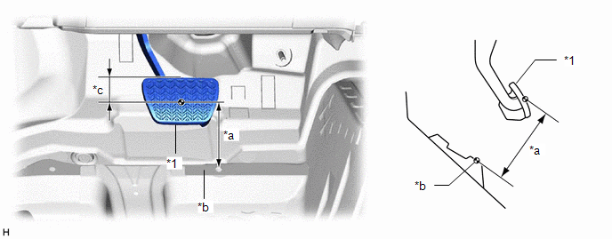
|
*1 | Brake Pedal Pad |
- | - |
|
*a | Brake Pedal Height |
*b | Measuring Plane of Floor Panel |
|
*c | 41 mm (1.61 in.) |
- | - |
Brake Pedal Height from Floor Panel:
149.5 to 159.5 mm (5.89 to 6.28 in.)
If the brake pedal height is not as specified, inspect and adjust the push rod length according to the procedure below.
(g) Adjust the push rod length.
| (1) Remove the stop light switch assembly. Click here
|
|
(2) Loosen the lock nut.
(3) Adjust the brake pedal height by turning the push rod.
Brake Pedal Height from Floor Panel:
149.5 to 159.5 mm (5.89 to 6.28 in.)
(4) Tighten the lock nut.
Torque:
26 N
READ NEXT:
 Installation
INSTALLATION PROCEDURE 1. INSTALL BRAKE PEDAL PAD
(a) Install the brake pedal pad to the brake pedal support assembly. 2. INSTALL STOP LIGHT SWITCH MOUNTING ADJUSTER
(a) Engage the 2 claws to inst
Precaution
PRECAUTION
NOTICE:
This vehicle is equipped with an SRS (Supplemental Restraint System). Failure to carry out service operations in the correct sequence could cause the SRS to unexpectedly deplo
SEE MORE:
Safety Connect services
■ Automatic Collision Notification
In case of either airbag deployment or severe rear-end collision, the
system is designed to automatically call the response center. The
responding agent receives the vehicle's location and attempts to
speak with the vehicle occupants to assess the level of em
Installation
INSTALLATION PROCEDURE 1. INSTALL CAMSHAFT TIMING GEAR BOLT
(a) Make sure that the No. 1 cylinder is at TDC/compression. HINT:
Check that the cutout of the camshaft timing gear assembly is at the top and align the timing mark (cutout) of the crankshaft pulley with the timing mark on the timing c
