Toyota Camry (XV70): Brake Pressure Sensor "A" Circuit Voltage Out of Range (C05401C,C054028,C054049)
DESCRIPTION
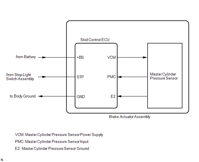
The master cylinder pressure sensor is connected to the skid control ECU in the brake actuator assembly.
|
DTC No. | Detection Item |
DTC Detection Condition | Trouble Area |
|---|---|---|---|
|
C05401C | Brake Pressure Sensor "A" Circuit Voltage Out of Range |
The voltage of the master cylinder pressure sensor signal is less than 0.129 V or more than 3.29 V for 0.1 seconds or more. |
Skid control ECU (brake actuator assembly) |
|
C054028 | Brake Pressure Sensor "A" Signal Bias Level Out of Range / Zero Adjustment Failure |
When the stop light switch assembly is off, the zero point of the master cylinder pressure sensor is less than -1.5 MPa (-15.3 kgf/cm2, -218 psi) or more than 1.5 MPa (15.3 kgf/cm2, 218 psi). |
Skid control ECU (brake actuator assembly) |
|
C054049 | Brake Pressure Sensor "A" Internal Electronic Failure |
An internal malfunction of the master cylinder pressure sensor is detected during the self test. |
Skid control ECU (brake actuator assembly) |
|
Vehicle Condition | |||
|---|---|---|---|
|
Pattern 1 | Pattern 2 | ||
|
Diagnosis Condition | - |
- | - |
|
Malfunction Status | The voltage of the master cylinder pressure sensor signal is less than 0.129 V. |
○ | - |
|
The voltage of the master cylinder pressure sensor signal is more than 3.29 V. |
- | ○ | |
|
Detection Time | 0.1 seconds or more. |
0.1 seconds or more. | |
|
Number of Trips | 1 trip |
1 trip | |
HINT:
DTC will be output when conditions for either of the patterns in the table above are met.
DTC Detection Conditions: C054028|
Vehicle Condition | |||
|---|---|---|---|
|
Pattern 1 | Pattern 2 | ||
|
Diagnosis Condition | The stop light switch assembly is off. |
○ | ○ |
|
Malfunction Status | The zero point of the master cylinder pressure sensor is less than -1.5 MPa (-15.3 kgf/cm2, -218 psi). |
○ | - |
|
The zero point of the master cylinder pressure sensor is more than 1.5 MPa (15.3 kgf/cm2, 218 psi). |
- | ○ | |
|
Detection Time | - |
- | |
|
Number of Trips | 1 trip |
1 trip | |
HINT:
DTC will be output when conditions for either of the patterns in the table above are met.
CAUTION / NOTICE / HINT
NOTICE:
After replacing the skid control ECU (brake actuator assembly), perform acceleration sensor zero point calibration and system information memorization.
Click here .gif)
PROCEDURE
| 1. |
REPLACE BRAKE ACTUATOR ASSEMBLY |
(a) Replace the skid control ECU (brake actuator assembly).
Click here
| NEXT | .gif) | END |
READ NEXT:
 Brake System Control Module "A" System Internal Failure (C059704)
DESCRIPTION The skid control ECU (brake actuator assembly) stores this DTC if malfunctions are found in a circuit inside the ECU by self diagnosis.
DTC No. Detection Item
DTC Detection Co
ECM Communication (C124A00)
DESCRIPTION If the vehicle information stored by the skid control ECU (brake actuator assembly) does not match that sent from the ECM or a new skid control ECU (brake actuator assembly) is installed a
Wheel Speed Sensor Signal Compare Failure (C124E62)
DESCRIPTION The skid control ECU (brake actuator assembly) measures the speed of each wheel by receiving signals from each speed sensor.
These signals are used for recognizing that all four wheels a
SEE MORE:
Installation
INSTALLATION PROCEDURE 1. INSTALL V-RIBBED BELT
HINT: When reusing the V-ribbed belt, check the ribs and back of the V-ribbed belt for wear and cracks. If wear or a crack that reaches the core (at more than 1 point) is found, replace the V-ribbed belt.
(a) Set the V-ribbed belt onto each pul
USB charging ports
The USB charging ports are used to supply 2.5 A (USB Type-A port)
or 3.0 A (USB Type-C port) of electricity at 5 V to external devices.
The USB charging ports are for charging only. They are not designed
for data transfer or other purposes.
Depending on the external device, it may not charge
