Toyota Camry (XV70): Check Mode Procedure
CHECK MODE PROCEDURE
HINT:
Compared to normal mode, check mode is more sensitive to malfunctions. Therefore, check mode can detect malfunctions that cannot be detected in normal mode.
NOTICE:
All the stored DTCs and freeze frame data are cleared if: 1) the ECM is changed from normal mode to check mode or vice versa; or 2) the engine switch is turned from on (IG) to ACC or off while in check mode. Before changing modes, always check and note any DTCs and freeze frame data.
CHECK MODE PROCEDURE
(a) Check and ensure the following conditions:
(1) Battery voltage is 11 V or higher.
(2) Throttle valve is fully closed.
(3) Shift lever is in P or N.
(4) A/C switch is off.
(b) Turn the engine switch off.
(c) Connect the Techstream to the DLC3.
(d) Turn the engine switch on (IG).
(e) Turn the Techstream on.
(f) Enter the following menus: Powertrain / Engine / Utility / Check Mode.
Powertrain > Engine > Utility|
Tester Display |
|---|
| Check Mode |
(g) Switch the ECM from normal mode to check mode.
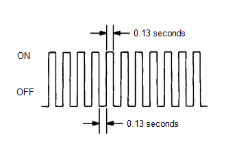
(h) Check that the MIL flashes as shown in the illustration.
(i) Start the engine.
(j) Check that the MIL turns off.
(k) Simulate the conditions of the malfunction described by the customer.
(l) Check the DTCs and freeze frame data using the Techstream.
READ NEXT:
 Fail-safe Chart
FAIL-SAFE CHART If any of the following DTCs are stored, the ECM enters fail-safe mode to allow the vehicle to be driven temporarily or stops fuel injection.
DTC Code Component
Fail-Safe
Data List / Active Test
DATA LIST / ACTIVE TEST DATA LIST HINT:
Using the Techstream to read the Data List allows the values or states of switches, sensors, actuators and other items to be read without removing any parts.
Diagnostic Trouble Code Chart
DIAGNOSTIC TROUBLE CODE CHART SFI System
DTC No. Detection Item
MIL Memory
Note Link
P001013 A Camshaft Position Actuator Bank 1 Circuit Open
Comes on DTC store
SEE MORE:
Throttle/Pedal Position Sensor/Switch "D" Circuit Short to Battery (P212012,P212014,P21201C,P21201F,P212099,P212512,P212514,P21251F,P21382B)
DESCRIPTION
HINT:
This Electronic Throttle Control System (ETCS) does not use a throttle cable.
These DTCs relate to the accelerator pedal position sensor.
The accelerator pedal position sensor is built into the accelerator pedal sensor assembly and has 2 sensor circuits: VPA (main) a
Display does not Dim when Light Control Switch is Turned ON
CAUTION / NOTICE / HINT
NOTICE:
Depending on the parts that are replaced during vehicle inspection or maintenance, performing initialization, registration or calibration may be needed. Refer to Precaution for Audio and Visual System.
Click here
When replacing the radio and display
