Toyota Camry (XV70): Components
COMPONENTS
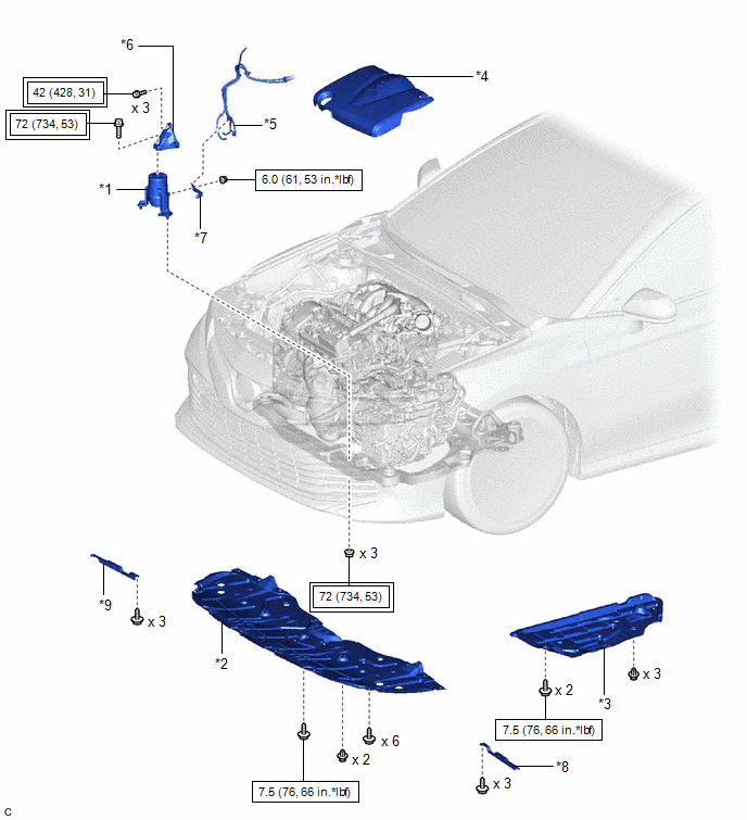
ILLUSTRATION
|
*1 | FRONT ENGINE MOUNTING INSULATOR |
*2 | NO. 1 ENGINE UNDER COVER |
|
*3 | REAR ENGINE UNDER COVER LH |
*4 | V-BANK COVER SUB-ASSEMBLY |
|
*5 | VACUUM HOSE |
*6 | FRONT ENGINE MOUNTING BRACKET |
|
*7 | STAY |
*8 | FRONT WHEEL OPENING EXTENSION PAD LH |
|
*9 | FRONT WHEEL OPENING EXTENSION PAD RH |
- | - |
.png) |
Tightening torque for "Major areas involving basic vehicle performance such as moving/turning/stopping": N*m (kgf*cm, ft.*lbf) |
.png) |
N*m (kgf*cm, ft.*lbf): Specified torque |
READ NEXT:
 On-vehicle Inspection
ON-VEHICLE INSPECTION CAUTION / NOTICE / HINT
HINT: Refer to Problem Symptoms Table. Click here
PROCEDURE
1. REMOVE FRONT WHEEL OPENING EXTENSION PAD LH Click here
2. REMOVE FRONT
Removal
REMOVAL PROCEDURE 1. REMOVE VACUUM SWITCHING VALVE (for Active Control Engine Mount System)
Click here 2. REMOVE V-BANK COVER SUB-ASSEMBLY
Click here
3. REMOVE FRONT WHEEL OPENING EX
Installation
INSTALLATION PROCEDURE 1. INSTALL FRONT ENGINE MOUNTING INSULATOR
(a) Install the stay to the front engine mounting insulator with the nut.
Torque: 6.0 N·m {61 kgf·cm, 53 in·lbf} (b) Install t
SEE MORE:
Removal
REMOVAL CAUTION / NOTICE / HINT
The necessary procedures (adjustment, calibration, initialization or registration) that must be performed after parts are removed and installed, or replaced during fuel pump assembly removal/installation are shown below. Necessary Procedures After Parts Removed/Inst
Installation
INSTALLATION CAUTION / NOTICE / HINT
CAUTION:
The engine assembly with transaxle is very heavy. Be sure to follow the procedure described in the repair manual, or the engine lifter may suddenly drop or the engine assembly with transaxle may fall off the engine lifter.
To prevent burns, do
© 2023-2025 Copyright www.tocamry.com
