Toyota Camry (XV70): Disassembly
DISASSEMBLY
PROCEDURE
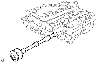
1. REMOVE MANUAL VALVE
| (a) Remove the manual valve from the transmission valve body assembly. |
|
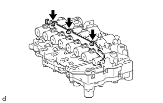
2. REMOVE SOLENOID LOCK PLATE
| (a) Remove the 3 bolts and solenoid lock plate from the transmission valve body assembly. |
|
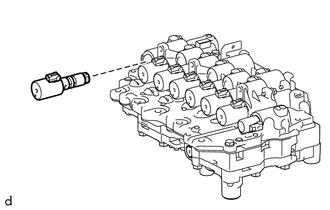
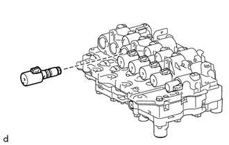
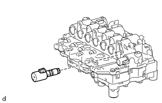
3. REMOVE SOLENOID (SLU) VALVE
| (a) Remove the solenoid (SLU) valve from the transmission valve body assembly. |
|
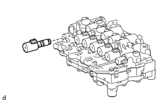
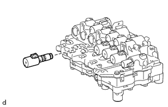
4. REMOVE SOLENOID (SL5) VALVE
| (a) Remove the solenoid (SL5) valve from the transmission valve body assembly. |
|
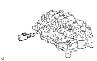
5. REMOVE SOLENOID (SL6) VALVE
| (a) Remove the solenoid (SL6) valve from the transmission valve body assembly. |
|
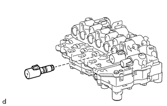
6. REMOVE SOLENOID (SL4) VALVE
| (a) Remove the solenoid (SL4) valve from the transmission valve body assembly. |
|
7. REMOVE SOLENOID (SL3) VALVE
| (a) Remove the solenoid (SL3) valve from the transmission valve body assembly. |
|
8. REMOVE SOLENOID (SL1) VALVE
| (a) Remove the solenoid (SL1) valve from the transmission valve body assembly. |
|
9. REMOVE SOLENOID (SL2) VALVE
| (a) Remove the solenoid (SL2) valve from the transmission valve body assembly. |
|
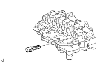
10. REMOVE SOLENOID (SLT) VALVE
| (a) Remove the solenoid (SLT) valve from the transmission valve body assembly. |
|
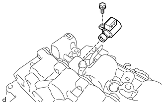
11. REMOVE SOLENOID (SL) VALVE
| (a) Remove the bolt and solenoid (SL) valve from the transmission valve body assembly. |
|
READ NEXT:
 Inspection
INSPECTION PROCEDURE 1. INSPECT SOLENOID (SL) VALVE
(a) Measure the resistance according to the value(s) in the table below.
Standard Resistance:
Tester Connection Condition
S
Reassembly
REASSEMBLY PROCEDURE 1. INSTALL SOLENOID (SL) VALVE
(a) Coat the solenoid (SL) valve with Toyota Genuine ATF WS.
(b) Install the solenoid (SL) valve to the transmission valv
Installation
INSTALLATION PROCEDURE 1. INSTALL TRANSMISSION VALVE BODY ASSEMBLY
(a) Coat 2 new transaxle case gaskets with Toyota Genuine ATF WS and install them to the automatic transaxle case sub-assembly.
(
SEE MORE:
Brake Hold Standby Indicator Light Circuit
DESCRIPTION The brake hold standby indicator light turns on if brake hold control is possible when the following conditions required for operation standby are met and the brake hold switch (electric parking brake switch assembly) is pressed while the ignition switch on.
Conditions required for
Components
COMPONENTS ILLUSTRATION
*1 REAR CENTER SEAT OUTER BELT ASSEMBLY
*2 REAR SEAT CUSHION ASSEMBLY
*3 REAR SEAT CUSHION LOCK HOOK
*4 REAR SEAT INNER BELT ASSEMBLY RH
*5 WASHER
- -
Tightening torque for "Major areas involving basic veh
