Toyota Camry (XV70): Electric Parking Brake System AUTO Function Circuit
DESCRIPTION
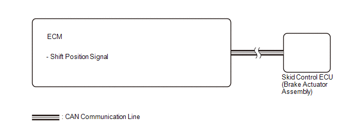
The skid control ECU (brake actuator assembly) receives shift position signals from the ECM via CAN communication to control the electric parking brake system AUTO function (shift-linked function).
The electric parking brake system AUTO function (shift-linked function) is automatically disabled when the ignition switch is ON, the brake pedal is depressed and the shift lever is moved out of P. Then, if the shift lever is moved to P, the AUTO function (shift-linked function) automatically operates to apply the electric parking brake.
WIRING DIAGRAM
CAUTION / NOTICE / HINT
NOTICE:
- The AUTO function (shift-linked function) will not be automatically disabled when the ignition switch is ON, the brake pedal is depressed and the shift lever is moved out from P if the electric parking brake switch is moved to the engage side. The AUTO function (shift-linked function) will not automatically operate to apply the electric parking brake when the shift lever is moved to P if the electric parking brake switch is moved to the release side.
PROCEDURE
|
1. | CHECK DTC (SFI SYSTEM) |
(a) Check for DTCs.
Powertrain > Engine > Trouble Codes|
Result | Proceed to |
|---|---|
|
DTC is not output | A |
|
DTC is output | B |
| A |
.gif) | REPLACE SKID CONTROL ECU (BRAKE ACTUATOR ASSEMBLY) |
| B |
| GO TO SFI SYSTEM for A25A-FKS: Click here for 2GR-FKS: Click here
|
.gif)
READ NEXT:
 Operation Method
OPERATION METHOD PROCEDURE 1. PRECAUTION
Click here 2. REMOVE REAR SEAT CUSHION ASSEMBLY
Click here
3. REMOVE REAR SEAT CUSHION LOCK HOOK
Click here
4. PARKING BRAKE FORCED RELEASE
SEE MORE:
Replacement
REPLACEMENT PROCEDURE 1. REMOVE FRONT WHEEL OPENING EXTENSION PAD RH
Click here
2. REMOVE FRONT WHEEL OPENING EXTENSION PAD LH Click here
3. REMOVE NO. 1 ENGINE UNDER COVER
Click here
4. REMOVE NO. 2 ENGINE UNDER COVER ASSEMBLY Click here
5. DRAIN TRANSFER OIL Cli
Terminals Of Ecu
TERMINALS OF ECU
Terminal No. (Symbol) Wiring Color
Terminal Description Condition
Specified Condition
K140-1 (+B) - K140-20 (E)
B - W-B Power source (+B)
Always 11 to 14 V
K140-3 (SIG-) - K140-20 (E)
GR - W-B Ground
Always Below
