Toyota Camry (XV70): Inspection
INSPECTION
PROCEDURE
1. INSPECT AND ADJUST BRAKE BOOSTER PUSH ROD
NOTICE:
Make the adjustment with no vacuum in the brake booster assembly. (Depress the brake pedal several times with the engine stopped.)
HINT:
- Adjustment of the brake booster push rod is required when the brake master cylinder sub-assembly is replaced with a new one.
- Adjustment is not necessary when the removed brake master cylinder sub-assembly is reused and the brake booster assembly is replaced with a new one.
(a) Apply chalk to the tip of the accessory tool.
HINT:
The accessory tool is included with a new brake master cylinder sub-assembly.
| (b) Place the accessory tool on the brake booster assembly. |
|
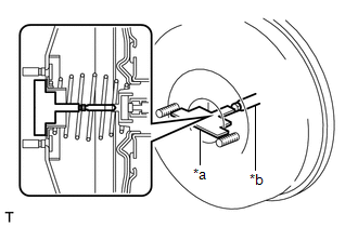
(c) Measure the clearance between the brake booster push rod and accessory tool.
Standard Clearance:
0 mm (0 in.)
HINT:
Adjust the clearance in the following cases:
- If there is clearance between the accessory tool and the shell of the brake booster (the accessory tool does not contact the body of the brake booster), the push rod is protruding too far.
- If the chalk does not stick on the tip of the brake booster push rod, the push rod protrusion length is insufficient.
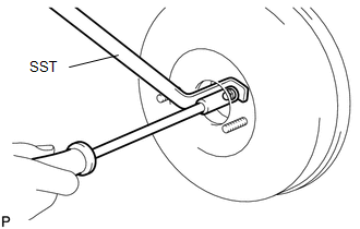
| (d) If the clearance is not as specified, adjust the push rod length by holding the push rod using SST and turning the tip of the push rod using a 7 mm socket driver. SST: 09737-00020 HINT: Check the push rod clearance again after adjustment. |
|
READ NEXT:
 Reassembly
REASSEMBLY PROCEDURE 1. INSTALL BRAKE MASTER CYLINDER RESERVOIR STRAINER
2. INSTALL BRAKE MASTER CYLINDER RESERVOIR FILLER CAP ASSEMBLY 3. INSTALL MASTER CYLINDER RESERVOIR GROMMET
(a) Apply a lig
Installation
INSTALLATION PROCEDURE 1. INSPECT AND ADJUST BRAKE BOOSTER PUSH ROD
Click here 2. INSTALL BRAKE MASTER CYLINDER O-RING
(a) Install a new brake master cylinder O-ring to the brake master cylinder
SEE MORE:
Freeze Frame Data
FREEZE FRAME DATA CHECK FREEZE FRAME DATA (a) Connect the Techstream to the DLC3.
(b) Turn the ignition switch to ON. (c) Turn the Techstream on.
(d) Enter the following menus: Body Electrical / Navigation System / Trouble Codes. Body Electrical > Navigation System > Trouble Codes
(e) Se
EVAP System Tank Vapor Line Restricted/Blocked (P00FE00)
DTC SUMMARY
DTC No. Detection Item
DTC Detection Condition Trouble Area
MIL Memory
Note P00FE00
EVAP System Tank Vapor Line Restricted/Blocked
Leak detection pump creates negative pressure (vacuum) in EVAP system and EVAP system pressure is measured. When t
