Toyota Camry (XV70): Inspection
INSPECTION
PROCEDURE
1. INSPECT FRONT DRIVE SHAFT ASSEMBLY
| (a) Check that there is no excessive play in the radial direction of the outboard joint. |
|
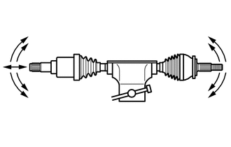
(b) Check that the inboard joint slides smoothly in the thrust direction.
(c) Check that there is no excessive play in the radial direction of the inboard joint.
(d) Check the boots for damage.
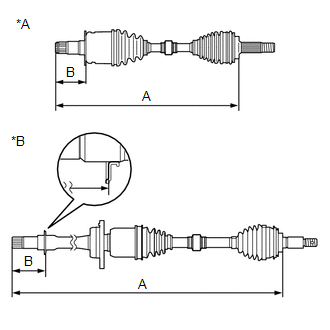
| (e) Check whether the drive shaft dimension (A) and (B) are within specification. NOTICE: Keep the drive shaft assembly level during inspection. Dimension (A):
Dimension (B):
|
|
READ NEXT:
 Reassembly
REASSEMBLY CAUTION / NOTICE / HINT
HINT:
Use the same procedure for the RH side and LH side.
The following procedure is for the LH side.
PROCEDURE 1. INSTALL FRONT AXLE OUTBOARD JOINT BO
Installation
INSTALLATION CAUTION / NOTICE / HINT
HINT:
Use the same procedure for the RH side and LH side.
The following procedure is for the LH side.
PROCEDURE 1. INSTALL FRONT DRIVE SHAFT HOLE SNA
SEE MORE:
Installation
INSTALLATION PROCEDURE 1. INSTALL TIMING CHAIN CASE OIL SEAL
(a) Apply MP grease to the lip of a new timing chain case oil seal.
*a Oil Seal Protrusion Height
(b) Using SST and a hammer, tap in the timing chain case oil seal until its surface is flus
Pressure Control Solenoid "A" Actuator Stuck Off (P07457F)
DESCRIPTION Based on signals from the transmission revolution sensors (NT and NC), the actual gear is detected.
The ECM compares the actual gear with the shift schedule in the ECM memory to detect mechanical malfunctions of the solenoid valves, transmission valve body assembly and automatic transa
© 2023-2025 Copyright www.tocamry.com
