Toyota Camry (XV70): Inspection
INSPECTION
PROCEDURE
1. INSPECT CAMSHAFT TIMING OIL CONTROL SOLENOID ASSEMBLY
HINT:
Use the same procedure for the intake side and exhaust side.
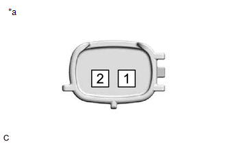
(a) Check the resistance.
| (1) Measure the resistance according to the value(s) in the table below. Standard Resistance:
If the result is not as specified, replace the camshaft timing oil control solenoid assembly. |
|
(b) Stroke Amount Inspection
| (1) Using vernier calipers, measure length (A) and (B) with the shaft of the camshaft timing oil control solenoid assembly set in the respective positions shown in the illustration. NOTICE: Do not apply battery voltage to the terminals of the camshaft timing oil control solenoid assembly. HINT: If the shaft does not extend under its own weight, extend the shaft with your fingers. |
|
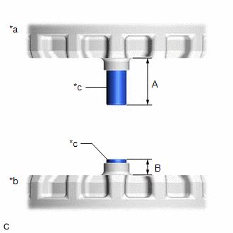
(2) Calculate the stroke amount based on the difference of length (A) and (B).
Standard:
6.5 mm (0.256 in.) or more
HINT:
Stroke amount = length (A) - length (B)
If the value is not as specified, replace the camshaft timing oil control solenoid assembly.
READ NEXT:
 Installation
INSTALLATION PROCEDURE 1. INSTALL CAMSHAFT TIMING OIL CONTROL SOLENOID ASSEMBLY (for Intake Side of Bank 2)
(a) Apply engine oil to a new O-ring and install it to the camshaft timing oil control
Components
COMPONENTS ILLUSTRATION
*1 FRONT FENDER APRON SEAL RH
*2 V-BANK COVER SUB-ASSEMBLY
N*m (kgf*cm, ft.*lbf): Specified torque
- - ILLUSTRATION
*1
SEE MORE:
Engine Coolant Temperature Sensor 1 Signal Stuck in Range (P01152A)
DESCRIPTION Refer to DTC P011511. Click here
DTC No. Detection Item
DTC Detection Condition Trouble Area
MIL Memory
Note P01152A
Engine Coolant Temperature Sensor 1 Signal Stuck in Range
Either of the following conditions is met (2 trip detection logic)
Installation
INSTALLATION CAUTION / NOTICE / HINT
NOTICE:
Because the left and right front flexible hoses are not interchangeable, verify the part number when installing the front flexible hoses.
When reusing the front flexible hoses, use the identification marks created during removal to install each
