Toyota Camry (XV70): Inspection
INSPECTION
PROCEDURE
1. INSPECT FUEL INJECTOR ASSEMBLY
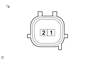
(a) Check the resistance.
| (1) Measure the resistance according to the value(s) in the table below. Standard Resistance:
If the result is not as specified, replace the fuel injector assembly. |
|
(b) Check the operation.
CAUTION:
Perform the inspection in a well-ventilated area.
Do not perform the inspection near an open flame.
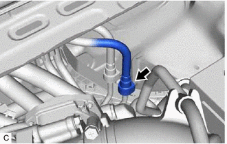
| (1) Disengage the 2 claws to remove the No. 2 fuel pipe clamp. |
|
.png)
| (2) Remove the No. 1 fuel pipe clamp from the fuel tube connector. |
|
.png)
| (3) Disconnect the fuel tube sub-assembly. Click here
|
|
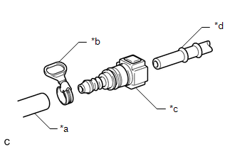
| (4) Connect SST (fuel tube connector) to SST (hose) with SST (hose band), and then connect them to the fuel pipe (vehicle side). SST: 09268-31015 09268-41500 09268-41700 95336-08070 NOTICE: Make sure the SST (fuel tube connector) O-rings are not damaged and are free of foreign matter as they are used to seal the connections between the fuel tube connector and fuel pipe. |
|
(5) Apply a light coat of gasoline to a new O-ring, and then install the O-ring to the fuel injector assembly.
| (6) Connect SST (adapter) and SST (hose) to the fuel injector assembly, and hold the fuel injector assembly and union with SST (clamp). SST: 09268-31015 09268-41600 09268-41300 09268-41700 95336-08070 |
|
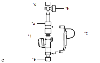
| (7) Tie SST (clamp) and SST (adapter) together with SST (tie band) as shown in the illustration. SST: 09268-31015 09268-41800 NOTICE:
HINT: When removing SST (tie band), disengage the lock. |
|
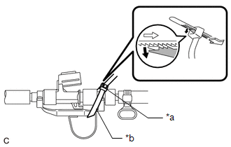
(8) Check that SST (clamp) and SST (adapter) cannot be easily separated.
(9) Install a vinyl tube to the fuel injector assembly.
CAUTION:
Install a suitable vinyl tube to the fuel injector assembly to prevent fuel from spraying.
(10) Set the fuel injector assembly into a graduated cylinder.
(11) Connect the Techstream to the DLC3.
(12) Turn the engine switch on (IG).
NOTICE:
Do not start the engine.
(13) Turn the Techstream on.
(14) Enter the following menus: Powertrain / Engine / Active Test / Activate the Circuit Relay.
Powertrain > Engine > Active Test|
Tester Display |
|---|
| Activate the Circuit Relay |
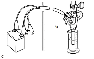
| (15) Connect SST (EFI inspection wire I) to the fuel injector assembly and battery for 15 seconds, and measure the injection volume with the graduated cylinder. Test each fuel injector assembly 2 or 3 times. SST: 09842-30090 Standard Injection Volume:
Difference between Each Fuel Injector Assembly: 14 cc (0.9 cu. in.) or less NOTICE:
If the injection volume is not as specified, replace the fuel injector assembly. |
|
(c) Check for leaks.
(1) Disconnect SST (EFI inspection wire I) from the battery and check for fuel leaks from the fuel injector assembly.
Standard Fuel Drop:
1 drop or less per 20 minutes
If the result is not as specified, replace the fuel injector assembly.
(2) Connect the fuel tube sub-assembly.
Click here
.gif)
(3) Install the No. 1 fuel pipe clamp to the fuel tube connector.
(4) Engage the 2 claws to install the No. 2 fuel pipe clamp.
(5) Check for fuel leaks.
Click here
