Toyota Camry (XV70): Inspection
INSPECTION
PROCEDURE
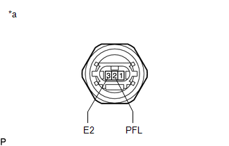
1. INSPECT FUEL PRESSURE SENSOR (FUEL DELIVERY PIPE WITH SENSOR ASSEMBLY)
NOTICE:
- Do not remove the fuel pressure sensor from the fuel delivery pipe with sensor assembly.
- If the fuel pressure sensor is removed, replace the fuel pressure sensor (fuel delivery pipe with sensor assembly) with a new one.
(a) Check the fuel pressure sensor output voltage.
| (1) Apply 5 V between terminals 1 (VC) and 3 (E2). NOTICE:
HINT: If a stable power supply is not available, connect 4 nickel-metal hydride batteries (1.2 V each) or equivalent in series. |
|
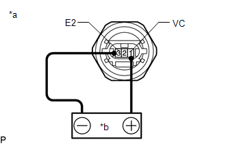
| (2) Measure the voltage according to the value(s) in the table below. Standard Voltage:
*: The output voltage changes depending on the voltage applied to the terminals. If the result is not as specified, replace the fuel pressure sensor (fuel delivery pipe with sensor assembly). |
|
READ NEXT:
 Installation
INSTALLATION PROCEDURE 1. INSTALL FUEL PRESSURE SENSOR (FUEL DELIVERY PIPE WITH SENSOR ASSEMBLY)
HINT: Perform "Inspection After Repair" after replacing the fuel pressure sensor (fuel delivery pipe
Components
COMPONENTS ILLUSTRATION
*A w/ Dust Cap
- -
*1 FUEL PRESSURE SENSOR (FUEL DELIVERY PIPE WITH SENSOR ASSEMBLY LH)
*2 FUEL PIPE PLUG SUB-ASSEMBLY
*3 DUST C
SEE MORE:
USB Audio System Recognition/Play Error
DESCRIPTION When a USB device or "iPod" is connected to the USB jack of the No. 1 stereo jack adapter assembly, it must have playable files. The device must also communicate with and be recognized by the radio and display receiver assembly. This diagnostic procedure is for when a device is not recog
HD Radio Tuner Malfunction (B1551,B158D,B15A0,B15B0,B15B3,B15B7,B15BA,B15F9)
DESCRIPTION These DTCs are stored when a malfunction occurs in the radio and display receiver assembly.
DTC No. Detection Item
DTC Detection Condition Trouble Area
B1551 HD Radio Tuner Malfunction
When any of the following conditions is met:
"HD Radio" tuner d
