Toyota Camry (XV70): Installation
INSTALLATION
PROCEDURE
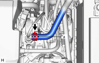
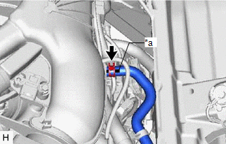
1. INSTALL NO. 1 VACUUM HOSE CONNECTOR (for A25A-FKS)
(a) Align the No. 1 vacuum hose connector with the vacuum pump assembly, and push them together until the No. 1 vacuum hose connector makes a "click" sound.
NOTICE:
- Check that there is no foreign matter on the connecting parts.
- After connecting the No. 1 vacuum hose connector, check that the vacuum pump assembly and No. 1 vacuum hose connector are securely connected by pulling on them.
(b) Connect the vacuum hose to the No. 1 vacuum hose connector.
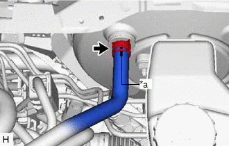
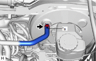
2. INSTALL UNION TO CHECK VALVE HOSE (for A25A-FKS)
(a) Install the 2 clips to the union to check valve hose.
| (b) Connect the union to check valve hose to the No. 1 vacuum hose connector, and slide the clip to secure it. NOTICE:
|
|
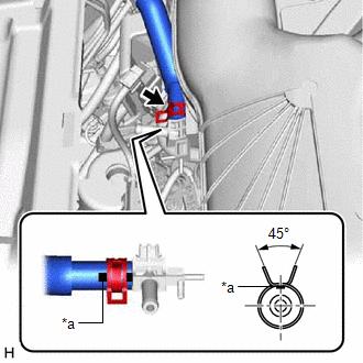
| (c) Connect the union to check valve hose to the brake booster assembly, and slide the clip to secure it. NOTICE:
|
|
3. INSTALL AIR TUBE (for 2GR-FKS)
| (a) Engage the clamp to install the air delivery way to the intake air surge tank assembly. |
|
.png)
(b) Install the 2 clips to the air tube.
| (c) Connect the air tube to the air delivery way, and slide the clip to secure it. NOTICE:
|
|
| (d) Connect the air tube to the vacuum pump assembly, and slide the clip to secure it. NOTICE:
|
|
| (e) Connect the 2 vacuum transmitting hose assemblies to the air delivery way. |
|
.png)
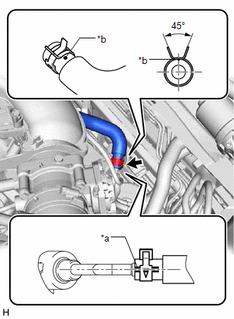
4. INSTALL UNION TO CHECK VALVE HOSE (for 2GR-FKS)
(a) Install the 2 clips to the union to check valve hose.
| (b) Connect the union to check valve hose to the air delivery way, and slide the clip to secure it. NOTICE:
|
|
| (c) Connect the union to check valve hose to the brake booster assembly, and slide the clip to secure it. NOTICE:
|
|
| (d) Engage the clamp to install the union to check valve hose to the air tube. |
|
.png)
5. INSTALL FRONT CENTER UPPER SUSPENSION BRACE SUB-ASSEMBLY (for 2GR-FKS)
Click here .gif)
6. INSTALL COWL TOP VENTILATOR LOUVER SUB-ASSEMBLY (for 2GR-FKS)
Click here
READ NEXT:
 Differential Oil
ComponentsCOMPONENTS ILLUSTRATION
*1 REAR DIFFERENTIAL FILLER PLUG
*2 REAR DIFFERENTIAL DRAIN PLUG
*3 GASKET
- -
N*m (kgf*cm, ft.*lbf): Specified t
Components
COMPONENTS ILLUSTRATION
*1 FRONT FLEXIBLE HOSE
*2 GASKET
*3 BRAKE LINE
*4 FRONT SPEED SENSOR
*5 UNION BOLT
- -
Tightening torque
SEE MORE:
Lost Communication with ECM / PCM "A" (U0100,U0125,U0126,U0129,U0142)
DESCRIPTION These DTCs are stored if there is a malfunction in the CAN communication system connected to the blind spot monitor sensor.
HINT: If CAN communication system DTCs are stored, they may also be stored for other systems. Blind Spot Monitor Master
DTC No. Detection Item
DTC De
Torque Converter Clutch Circuit Short to Ground (P074011)
DESCRIPTION Solenoid (SL) valve is turned on and off by signals from the ECM to control the hydraulic pressure acting on the lock-up relay valve, which then controls operation of the lock-up clutch.
DTC No. Detection Item
DTC Detection Condition Trouble Area
MIL Memory
Not
