Toyota Camry (XV70): Left Rear Wheel Speed Sensor Circuit Short to Battery (C050C12)
DESCRIPTION
Each speed sensor detects wheel speed and sends signals to the skid control ECU (brake actuator assembly). These signals are used by the ABS control.
The speed sensor detects the magnetic fields of the speed sensor rotor as it rotates and outputs a pulse signal.
The frequency of the pulse varies in accordance with the rotational speed of the speed sensor rotor and the system uses this to determine the wheel speed.
|
DTC No. | Detection Item |
DTC Detection Condition | Trouble Area |
|---|---|---|---|
|
C050C12 | Left Rear Wheel Speed Sensor Circuit Short to Battery |
A short to +B in the speed sensor signal circuit is detected for 0.12 seconds or more. |
|
*1: for 2WD
*2: for AWD
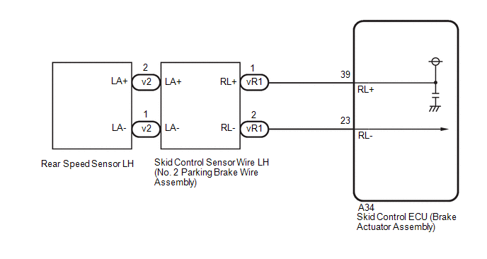
WIRING DIAGRAM
for 2WD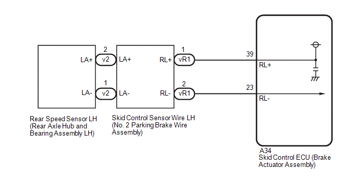 for AWD
CAUTION / NOTICE / HINT
NOTICE:
- After replacing the skid control ECU (brake actuator assembly), perform acceleration sensor zero point calibration and system information memorization.
Click here
.gif)
- After replacing or removing and installing a speed sensor, perform Dealer Mode (Signal Check) inspection to confirm that the speed sensors are operating correctly.
Click here
PROCEDURE
|
1. | CHECK VEHICLE |
(a) Check the vehicle specification.
| Result |
Proceed to |
|---|---|
| for 2WD |
A |
| for AWD |
B |
| B |
.gif) | GO TO STEP 6 |
|
.gif)
| 2. |
CHECK HARNESS AND CONNECTOR (SENSOR GROUND CIRCUIT) |
| (a) Make sure that there is no looseness at the locking part and the connecting part of the connectors. OK: The connector is securely connected. |
|

(b) Disconnect the v2 rear speed sensor LH (rear axle hub and bearing assembly LH) connector.
(c) Check both the connector case and the terminals for deformation and corrosion.
OK:
No deformation or corrosion.
(d) Turn the ignition switch to ON.
(e) Measure the voltage according to the value(s) in the table below.
Standard Voltage:
|
Tester Connection | Condition |
Specified Condition |
|---|---|---|
|
v2-2 (LA+) - v2-1 (LA-) |
Ignition switch on | 11 to 14 V |
| OK | | REPLACE REAR AXLE HUB AND BEARING ASSEMBLY LH |
|
| 3. |
CHECK HARNESS AND CONNECTOR (SENSOR GROUND CIRCUIT) |
| (a) Make sure that there is no looseness at the locking part and the connecting part of the connectors. OK: The connector is securely connected. |
|
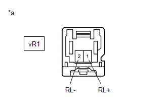
(b) Disconnect the vR1 skid control sensor wire LH (No. 2 parking brake wire assembly) connector.
(c) Check both the connector case and the terminals for deformation and corrosion.
OK:
No deformation or corrosion.
(d) Turn the ignition switch to ON.
(e) Measure the voltage according to the value(s) in the table below.
Standard Voltage:
|
Tester Connection | Condition |
Specified Condition |
|---|---|---|
|
vR1-1 (RL+) - vR1-2 (RL-) |
Ignition switch on | 11 to 14 V |
| OK | | REPLACE NO. 2 PARKING BRAKE WIRE ASSEMBLY |
|
| 4. |
CHECK HARNESS AND CONNECTOR (NO. 2 PARKING BRAKE WIRE ASSEMBLY - BRAKE ACTUATOR ASSEMBLY) |
| (a) Make sure that there is no looseness at the locking part and the connecting part of the connectors. OK: The connector is securely connected. |
|
(b) Disconnect the A34 skid control ECU (brake actuator assembly) connector.
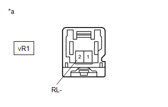
(c) Disconnect the vR1 skid control sensor wire LH (No. 2 parking brake wire assembly) connector.
(d) Check both the connector case and the terminals for deformation and corrosion.
OK:
No deformation or corrosion.
(e) Measure the voltage according to the value(s) in the table below.
Standard Voltage:
|
Tester Connection | Condition |
Specified Condition |
|---|---|---|
|
vR1-2 (RL-) - Body ground |
Always | Below 1.5 V |
| NG | | REPAIR OR REPLACE HARNESS OR CONNECTOR |
|
| 5. |
CHECK HARNESS AND CONNECTOR (NO. 2 PARKING BRAKE WIRE ASSEMBLY - BRAKE ACTUATOR ASSEMBLY) |
(a) Make sure that there is no looseness at the locking part and the connecting part of the connectors.
OK:
The connector is securely connected.
(b) Disconnect the A34 skid control ECU (brake actuator assembly) connector.
(c) Disconnect the vR1 skid control sensor wire LH (No. 2 parking brake wire assembly) connector.
(d) Check both the connector case and the terminals for deformation and corrosion.
OK:
No deformation or corrosion.
(e) Measure the resistance according to the value(s) in the table below.
Standard Resistance:
|
Tester Connection | Condition |
Specified Condition |
|---|---|---|
|
vR1-1 (RL+) or A34-39 (RL+) - vR1-2 (RL-) or A34-23 (RL-) |
Always | 10 kΩ or higher |
| OK | | REPLACE BRAKE ACTUATOR ASSEMBLY |
| NG | | REPAIR OR REPLACE HARNESS OR CONNECTOR |
| 6. |
CHECK HARNESS AND CONNECTOR (SENSOR GROUND CIRCUIT) |
| (a) Make sure that there is no looseness at the locking part and the connecting part of the connectors. OK: The connector is securely connected. |
|
(b) Disconnect the v2 rear speed sensor LH connector.
(c) Check both the connector case and the terminals for deformation and corrosion.
OK:
No deformation or corrosion.
(d) Turn the ignition switch to ON.
(e) Measure the voltage according to the value(s) in the table below.
Standard Voltage:
|
Tester Connection | Condition |
Specified Condition |
|---|---|---|
|
v2-2 (LA+) - v2-1 (LA-) |
Ignition switch on | 11 to 14 V |
| OK | | REPLACE REAR SPEED SENSOR LH |
| NG | | GO TO STEP 3 |
READ NEXT:
 Left Rear Wheel Speed Sensor Circuit Short to Ground or Open (C050C14)
DESCRIPTION Refer to DTC C050C12 Click here
DTC No. Detection Item
DTC Detection Condition Trouble Area
C050C14 Left Rear Wheel Speed Sensor Circuit Short to Ground or Ope
Left Rear Wheel Speed Sensor Circuit Voltage Out of Range (C050C1C)
DESCRIPTION Refer to DTC C050C12 Click here
DTC No. Detection Item
DTC Detection Condition Trouble Area
C050C1C Left Rear Wheel Speed Sensor Circuit Voltage Out of Range
Left Rear Wheel Speed Sensor Circuit Intermittent (C050C1F)
DESCRIPTION Refer to DTC C050C12 Click here
DTC No. Detection Item
DTC Detection Condition Trouble Area
C050C1F Left Rear Wheel Speed Sensor Circuit Intermittent
SEE MORE:
Evaporative Emission System Incorrect Purge Flow Actuator Stuck On (P04417E,P04417F,P04419C)
DTC SUMMARY
DTC No. Detection Item
DTC Detection Condition Trouble Area
MIL Memory
Note P04417E
Evaporative Emission System Incorrect Purge Flow Actuator Stuck On
Leak detection pump creates negative pressure (vacuum) in EVAP system and EVAP system pressure
A/F (O2) Sensor Positive Current Control Bank 1 Sensor 1 Circuit Short to Ground (P223711,...,P225412)
DESCRIPTION Refer to DTC P219519. Click here
HINT: Although the DTC titles say O2 sensor, these DTCs relate to the air fuel ratio sensor.
DTC No. Detection Item
DTC Detection Condition Trouble Area
MIL Memory
Note P223711
A/F (O2) Sensor Positive Current Cont
