Toyota Camry (XV70): MIL Circuit
DESCRIPTION
The Malfunction Indicator Lamp (MIL) is used to indicate vehicle malfunctions detected by the ECM.
The MIL operation can be checked visually. When the engine switch is first turned on (IG), the MIL should be illuminated and should then turn off after the engine is started. If the MIL remains illuminated or is not illuminated, conduct the following troubleshooting procedure using the Techstream.
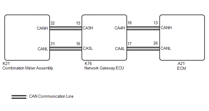
WIRING DIAGRAM
PROCEDURE
| 1. |
CHECK THAT MIL IS ILLUMINATED |
(a) Perform troubleshooting in accordance with the table below.
|
MIL | Condition |
Proceed to |
|---|---|---|
| Illuminates → Turns off |
Engine switch on (IG) → engine is started |
A |
| Other than above |
- | B |
| A |
.gif) | CHECK FOR INTERMITTENT PROBLEMS |
|
.gif)
| 2. |
CHECK COMMUNICATION BETWEEN TECHSTREAM AND ECM |
(a) Connect the Techstream to the DLC3.
(b) Turn the engine switch on (IG).
(c) Turn the Techstream on.
(d) Check the communication between the Techstream and ECM.
HINT:
It can be checked using the "Engine" item of the Data List.
|
Result | Proceed to |
|---|---|
|
Communication is possible |
A |
| Communication is not possible |
B |
| B |
| GO TO VC OUTPUT CIRCUIT |
|
| 3. |
CHECK WHETHER DTC OUTPUT RECURS |
(a) Connect the Techstream to the DLC3.
(b) Turn the engine switch on (IG).
(c) Turn the Techstream on.
(d) Enter the following menus: System Select / Health Check.
(e) Check if any DTCs have been detected. Note down any DTCs.
|
Result | Proceed to |
|---|---|
|
DTCs are not output | A |
|
Any DTCs is output | B |
HINT:
Check for detected DTCs output from other ECUs which relate to the MIL.
| B |
| REPAIR CIRCUIT INDICATED BY OUTPUT |
|
| 4. |
PERFORM ACTIVE TEST USING TECHSTREAM |
(a) Connect the Techstream to the DLC3.
(b) Turn the engine switch on (IG).
(c) Turn the Techstream on.
(d) Enter the following menus: Body Electrical / Combination Meter / Active Test / Check Engine Indicator.
Body Electrical > Combination Meter > Active Test|
Tester Display |
|---|
| Check Engine Indicator |
(e) Check the status of the MIL while performing the Active Test.
|
Result | Proceed to |
|---|---|
|
Changes | A |
|
Does not change | B |
| A |
| REPLACE ECM
|
.gif)
| B |
| REPLACE COMBINATION METER ASSEMBLY
|
READ NEXT:
 Ignition Circuit
DESCRIPTION A direct ignition system is used on this vehicle. The direct ignition system is a 1 cylinder ignition system which ignites one cylinder with one ignition coil. In the 1 cylinder ignition s
Drive Start Control
DESCRIPTION The drive start control is controlled by the ECM.
If the ECM determines that the shift lever and accelerator pedal are operated abnormally, engine output is restricted and, when necessar
Rough Idling
DESCRIPTION
Problem Symptom Suspected Area
Trouble Area
Engine speed fluctuation due to abnormal combustion
Idle speed too low or high
Strong engine vibration due
SEE MORE:
Installation
INSTALLATION PROCEDURE 1. PRECAUTION
NOTICE:
When replacing the radio and display receiver assembly or navigation ECU, always replace it with a new one. If a radio and display receiver assembly or navigation ECU which was installed to another vehicle is used, the following may occur:
A c
Multi-axis Acceleration Sensor Module "A" Circuit Voltage Out of Range (C05201C)
DESCRIPTION The airbag sensor assembly has a built-in yaw rate and acceleration sensor and detects the vehicle condition.
When the skid control ECU (brake actuator assembly) detects an abnormal acceleration sensor (airbag sensor assembly) signal, or the control value calculated using the accelerat
