Toyota Camry (XV70): Removal
REMOVAL
CAUTION / NOTICE / HINT
The necessary procedures (adjustment, calibration, initialization or registration) that must be performed after parts are removed and installed, or replaced battery removal/installation are shown below.
Necessary Procedures After Parts Removed/Installed/Replaced|
Replaced Part or Performed Procedure |
Necessary Procedure | Effect/Inoperative Function when Necessary Procedure not Performed |
Link |
|---|---|---|---|
|
Battery terminal is disconnected/reconnected |
Perform steering sensor zero point calibration |
Lane Tracing Assist System |
|
|
Pre-collision System | |||
|
Memorize steering angle neutral point |
Parking assist monitor system |
| |
|
Panoramic view monitor system |
|
PROCEDURE
1. PRECAUTION
NOTICE:
- After turning the engine switch off, waiting time may be required before disconnecting the cable from the negative (-) battery terminal. Therefore, make sure to read the disconnecting the cable from the negative (-) battery terminal notices before proceeding with work.
Click here
.gif)
- When replacing the battery, use a new battery of the same dimensions with a capacity of 70 Ah or more at a 20-hour rate.
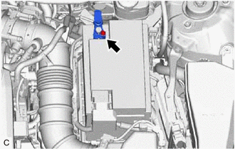
2. DISCONNECT CABLE FROM NEGATIVE BATTERY TERMINAL
| (a) Loosen the nut, and disconnect the cable from the negative (-) battery terminal. NOTICE: When disconnecting the cable, some systems need to be initialized after the cable is reconnected. Click here |
|
3. REMOVE BATTERY
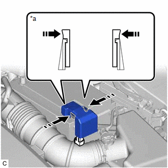
(a) Disengage the 2 claws and remove the battery terminal cap from the positive (+) battery terminal in the order shown in the illustration.
|
*a | Side View of Claws |
 |
Push Battery Terminal Cap Here |
 |
Push |
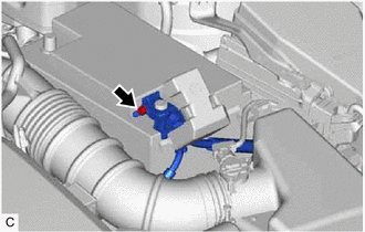
| (b) Loosen the nut and disconnect the cable from the positive (+) battery terminal. |
|
| (c) Remove the bolt and No. 2 battery clamp from the battery clamp sub-assembly. |
|
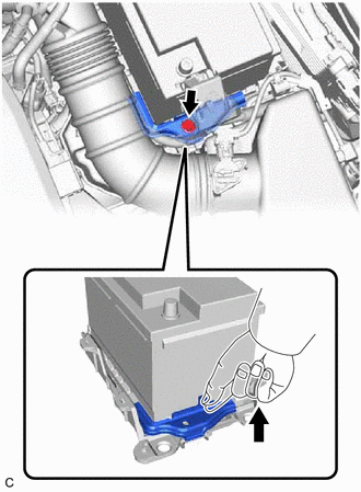
(d) Remove the battery from the vehicle.
READ NEXT:
 Installation
INSTALLATION PROCEDURE 1. INSTALL BATTERY
(a) Install the battery to the vehicle.
(b) Install the No. 2 battery clamp to the battery clamp sub-assembly with the bolt.
Torque: 18.5 N
2gr-fks Coolant
ComponentsCOMPONENTS ILLUSTRATION
*1 RADIATOR CAP SUB-ASSEMBLY
*2 RADIATOR DRAIN COCK PLUG
*3 NO. 1 ENGINE UNDER COVER
- - ReplacementREPLACEMENT CAUTION / NOT
2gr-fks Drive Belt
ComponentsCOMPONENTS ILLUSTRATION
*1 FRONT FENDER APRON SEAL RH
*2 V-RIBBED BELT RemovalREMOVAL PROCEDURE
1. REMOVE FRONT WHEEL RH Click here
2. REMOVE FRONT FENDER APRON
SEE MORE:
Portable Player cannot be Operated Using In-vehicle Device or Track Information is not Displayed on In-vehicle Device
PROCEDURE
1. CHECK USING ANOTHER "Bluetooth" AUDIO COMPATIBLE VEHICLE OF SAME MODEL
(a) Check if track information is displayed normally on another "Bluetooth" audio compatible vehicle of the same model.
OK: Track information is displayed normally.
OK
PROCEED TO NEXT SUSP
Black Screen
PROCEDURE
1. CHECK DISPLAY SETTING
(a) Check that the display is not in screen off mode. OK: The display setting is not in screen off mode.
NG
CHANGE SCREEN TO SCREEN ON MODE
OK
2.
CHECK IMAGE QUALITY SETTING (a) Check that the
