Toyota Camry (XV70): Removal
REMOVAL
CAUTION / NOTICE / HINT
The necessary procedures (adjustment, calibration, initialization or registration) that must be performed after parts are removed and installed, or replaced during brake booster assembly removal/installation are shown below.
Necessary Procedures After Parts Removed/Installed/Replaced|
Replaced Part or Performed Procedure |
Necessary Procedure | Effect/Inoperative Function when Necessary Procedure not Performed |
Link |
|---|---|---|---|
|
Disconnect cable from negative battery terminal |
Perform steering sensor zero point calibration |
Lane tracing assist system |
|
|
Pre-collision system | |||
|
Memorize steering angle neutral point |
Parking assist monitor system |
| |
|
Panoramic view monitor system |
|
CAUTION / NOTICE / HINT
NOTICE:
Make sure to release vacuum from the brake booster assembly before removing the brake master cylinder sub-assembly from the brake booster assembly.
PROCEDURE
1. PRECAUTION
NOTICE:
After turning the ignition switch off, waiting time may be required before disconnecting the cable from the negative (-) battery terminal. Therefore, make sure to read the disconnecting the cable from the negative (-) battery terminal notices before proceeding with work.
Click here .gif)
2. REMOVE BRAKE MASTER CYLINDER SUB-ASSEMBLY
Click here
3. REMOVE NO. 1 INSTRUMENT PANEL UNDER COVER SUB-ASSEMBLY
Click here
4. REMOVE COWL TOP VENTILATOR LOUVER SUB-ASSEMBLY
Click here
5. REMOVE FRONT CENTER UPPER SUSPENSION BRACE SUB-ASSEMBLY
Click here
6. REMOVE NO. 1 ENGINE COVER SUB-ASSEMBLY (for A25A-FKS)
Click here
7. REMOVE AIR CLEANER ASSEMBLY WITH AIR CLEANER HOSE (for A25A-FKS)
Click here
8. REMOVE AIR CLEANER ASSEMBLY WITH AIR CLEANER HOSE (for 2GR-FKS)
Click here
9. REMOVE BATTERY CLAMP SUB-ASSEMBLY
(a) for A25A-FKS:
| (1) Disengage the 4 clamps from the battery clamp sub-assembly. |
|
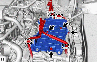
(2) Remove the 3 bolts, nut and battery clamp sub-assembly.
(b) for 2GR-FKS:
| (1) Disengage the 5 clamps from the battery clamp sub-assembly. |
|
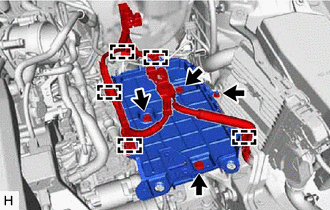
(2) Remove the 3 bolts, nut and battery clamp sub-assembly.
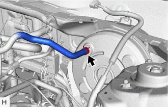
10. DISCONNECT UNION TO CHECK VALVE HOSE
| (a) Slide the clip and disconnect the union to check valve hose from the brake booster assembly. |
|
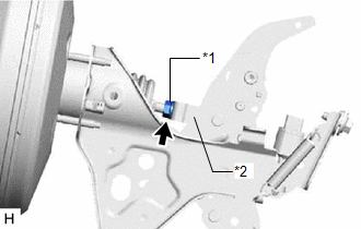
11. LOOSEN LOCK NUT
| (a) Loosen the lock nut of the brake master cylinder push rod clevis. |
|
12. REMOVE PUSH ROD PIN
Click here
13. REMOVE BRAKE BOOSTER ASSEMBLY
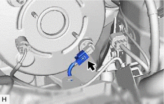
| (a) Disconnect the connector from the vacuum warning switch assembly. |
|
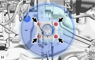
| (b) Remove the 4 nuts and push the brake booster assembly toward the engine compartment. NOTICE: Do not apply excessive force to the brake lines. |
|
(c) Remove the brake master cylinder push rod clevis and lock nut from the brake booster assembly.
(d) Remove the brake booster assembly from the vehicle body.
NOTICE:
Do not apply excessive force to the brake lines.
14. REMOVE BRAKE BOOSTER GASKET
READ NEXT:
 Disassembly
DISASSEMBLY PROCEDURE 1. REMOVE BRAKE VACUUM CHECK VALVE ASSEMBLY
(a) Remove the brake vacuum check valve assembly from the brake booster assembly.
(b) Remove the check valve grommet from the brak
Inspection
INSPECTION PROCEDURE 1. INSPECT BRAKE VACUUM CHECK VALVE ASSEMBLY
(a) Check that there is ventilation from the booster side to the engine side, and no ventilation from the engine side to the boo
Reassembly
REASSEMBLY PROCEDURE 1. INSTALL VACUUM WARNING SWITCH ASSEMBLY
(a) Install a new check valve grommet to the brake booster assembly. (b) Install the vacuum warning switch assembly to the brake booste
SEE MORE:
Uniform Tire Quality Grading
This information has been prepared in accordance with regulations
issued by the National Highway Traffic Safety Administration of the
U.S. Department of Transportation.
It provides the purchasers and/or prospective purchasers of Toyota
vehicles with information on uniform tire quality grading.
VSC does not Operate or VSC does not Operate Correctly
DESCRIPTION When TRAC or VSC is operating, the skid control ECU (brake actuator assembly) blinks the slip indicator light to inform the driver that slippage occurred.
When a communication malfunction with the ECM is detected, TRAC and VSC are disabled. Also, TRAC and VSC are disabled when a DTC is
