Toyota Camry (XV70): Removal
REMOVAL
CAUTION / NOTICE / HINT
The necessary procedures (adjustment, calibration, initialization, or registration) that must be performed after parts are removed and installed, or replaced during No. 1 parking brake cable assembly removal/installation are shown below.
Necessary Procedures After Parts Removed/Installed/Replaced|
Replaced Part or Performed Procedure |
Necessary Procedure | Effect/Inoperative Function when Necessary Procedure not Performed |
Link |
|---|---|---|---|
|
*1: When performing learning using the Techstream.
Click here | |||
|
Disconnect cable from negative battery terminal |
Perform steering sensor zero point calibration |
Lane Tracing Assist System |
|
|
Pre-collision system | |||
|
Parking Support Brake System*1 | |||
|
Memorize steering angle neutral point |
Parking assist monitor system |
| |
|
Panoramic view monitor system |
| ||
|
Removal/installation of the front passenger seat |
Zero point calibration (Occupant classification system) |
|
|
PROCEDURE
1. REMOVE PARKING BRAKE PEDAL ASSEMBLY
Click here
.gif)
2. REMOVE FRONT SEAT ASSEMBLY LH
for Power Seat: Click here
for Manual Seat: Click here
3. REMOVE FRONT SEAT ASSEMBLY RH
for Power Seat: Click here
for Manual Seat: Click here
4. REMOVE CONSOLE BOX ASSEMBLY
Click here
5. REMOVE REAR SEAT CUSHION ASSEMBLY
for Fold Down Seat Type: Click here
for Fixed Seat Type: Click here
6. REMOVE REAR SEAT CUSHION LOCK HOOK
for Fold Down Seat Type: Click here
for Fixed Seat Type: Click here
7. DISCONNECT FRONT DOOR OPENING TRIM WEATHERSTRIP LH
Click here
8. REMOVE REAR DOOR SCUFF PLATE LH
Click here
9. DISCONNECT REAR DOOR OPENING TRIM WEATHERSTRIP LH
Click here
10. REMOVE LOWER CENTER PILLAR GARNISH LH
Click here
11. REMOVE FRONT DOOR SCUFF PLATE RH
HINT:
Use the same procedure as for the LH side.
12. REMOVE COWL SIDE TRIM SUB-ASSEMBLY RH
HINT:
Use the same procedure as for the LH side.
13. DISCONNECT FRONT DOOR OPENING TRIM WEATHERSTRIP RH
HINT:
Use the same procedure as for the LH side.
14. REMOVE REAR DOOR SCUFF PLATE RH
HINT:
Use the same procedure as for the LH side.
15. DISCONNECT REAR DOOR OPENING TRIM WEATHERSTRIP RH
HINT:
Use the same procedure as for the LH side.
16. REMOVE LOWER CENTER PILLAR GARNISH RH
HINT:
Use the same procedure as for the LH side.
17. REMOVE NO. 2 INSTRUMENT PANEL UNDER COVER SUB-ASSEMBLY
Click here
18. REMOVE ACCELERATOR PEDAL
Click here
19. DISCONNECT FRONT FLOOR CARPET ASSEMBLY
(a) for LH Side:
(1) Using a clip remover, remove the 2 front floor carpet clips.
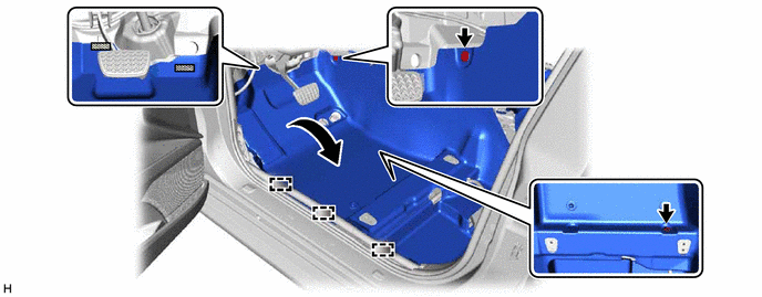
.png) |
Fastener | - |
- |
(2) Disengage the 3 guides.
(3) Disengage each fastener and turn back the front floor carpet assembly as shown in the illustration.
(b) for RH Side:
(1) Using a clip remover, remove the 2 front floor carpet clips.
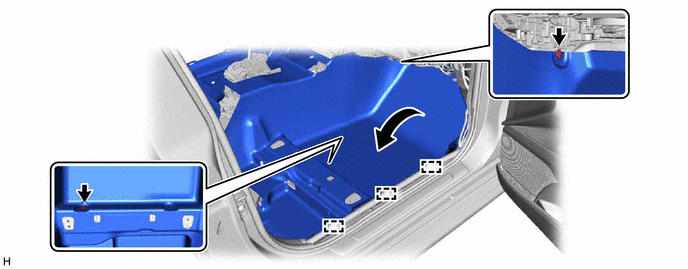
(2) Disengage the 3 guides.
(3) Turn back the front floor carpet assembly as shown in the illustration.
20. REMOVE REAR NO. 2 AIR DUCT
(a) Disengage the 4 claws to remove the rear No. 2 air duct as shown in the illustration.
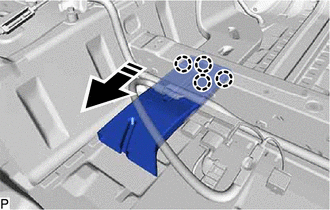
.png) |
Remove in this Direction |
21. REMOVE REAR NO. 1 AIR DUCT
Click here
22. REMOVE NO. 1 CONSOLE BOX DUCT (for Dual Type)
(a) Remove the clip.
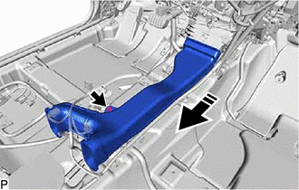
|
|
Remove in this Direction |
(b) Remove the No. 1 console box duct as shown in the illustration.
23. REMOVE NO. 2 INDOOR ELECTRICAL KEY ANTENNA ASSEMBLY (w/ Smart Key System)
Click here
24. SEPARATE NO. 1 PARKING BRAKE CABLE ASSEMBLY
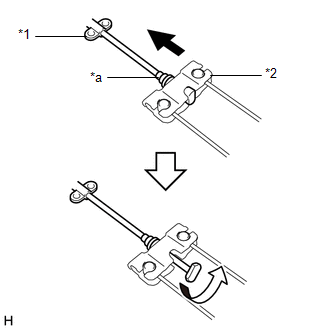
(a) for Type A:
| (1) Separate the No. 1 parking brake cable assembly from the No. 1 parking brake pull rod sub-assembly as shown in the illustration. |
|
(b) for Type B:
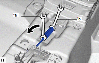
| (1) Slide the rubber boot as shown in the illustration. |
|
(2) Separate the No. 1 parking brake cable assembly from the parking brake equalizer as shown in the illustration.
25. REMOVE BRAKE PEDAL SUPPORT ASSEMBLY
Click here
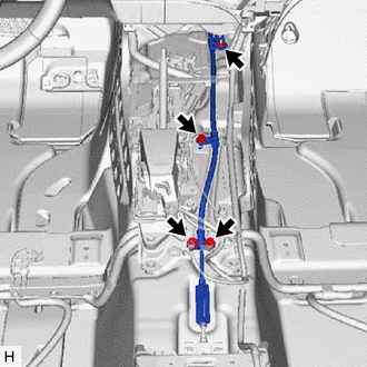
26. REMOVE NO. 1 PARKING BRAKE CABLE ASSEMBLY
| (a) Disengage the 4 clamps. |
|
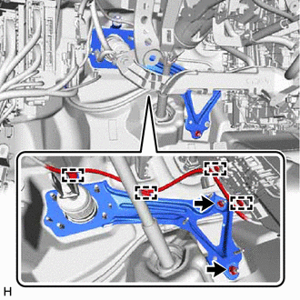
(b) Remove the 2 nuts, and separate the brake pedal support base from the vehicle body.
NOTICE:
Do not damage the air conditioner unit assembly when separating the brake pedal support base from the vehicle.
HINT:
Separate the brake pedal support base just enough to gain access to the nut of the No. 1 parking brake cable assembly.
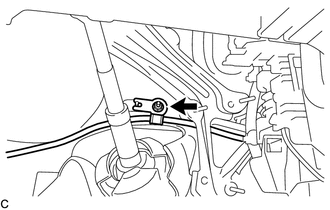
| (c) Remove the nut. |
|
| (d) Remove the 3 bolts, nut and No. 1 parking brake cable assembly. |
|
READ NEXT:
 Installation
INSTALLATION PROCEDURE 1. INSTALL NO. 1 PARKING BRAKE CABLE ASSEMBLY
(a) Install the No. 1 parking brake cable assembly with the 3 bolts and nut.
Torque: Bolt: : 15.5 N
Components
COMPONENTS ILLUSTRATION
*1 REAR CENTER SEAT OUTER BELT ASSEMBLY
*2 REAR SEAT CUSHION ASSEMBLY
*3 REAR SEAT CUSHION LOCK HOOK
*4 REAR SEAT INNER BELT ASSEMBLY RH
SEE MORE:
2gr-fks Spark Plug
ComponentsCOMPONENTS ILLUSTRATION
*1 IGNITION COIL ASSEMBLY
*2 SPARK PLUG
*3 V-BANK COVER SUB-ASSEMBLY
*4 VACUUM HOSE
N*m (kgf*cm, ft.*lbf): Specified torque
- - RemovalREMOVAL CAUTION / NOTICE / HINT
The necessary procedures (adjustm
Right Rear Wheel Speed Sensor Circuit Voltage Out of Range (C05121C)
DESCRIPTION Refer to DTC C051212 Click here
DTC No. Detection Item
DTC Detection Condition Trouble Area
C05121C Right Rear Wheel Speed Sensor Circuit Voltage Out of Range
When the vehicle is being driven in a straight line at a speed of 20 km/h (12 mph) or mor
