Toyota Camry (XV70): Removal
REMOVAL
CAUTION / NOTICE / HINT
The necessary procedures (adjustment, calibration, initialization, or registration) that must be performed after parts are removed and installed, or replaced during No. 3 parking brake cable assembly removal/installation are shown below.
Necessary Procedures After Parts Removed/Installed/Replaced|
Replaced Part or Performed Procedure |
Necessary Procedure | Effect/Inoperative Function when Necessary Procedure not Performed |
Link |
|---|---|---|---|
|
*: When performing learning using the Techstream.
Click here | |||
|
Disconnect cable from negative battery terminal |
Perform steering sensor zero point calibration |
Lane Tracing Assist System |
|
|
Pre-collision system | |||
|
Parking Support Brake System*1 | |||
|
Memorize steering angle neutral point |
Parking assist monitor system |
| |
|
Panoramic view monitor system |
| ||
|
Removal/installation of the front passenger seat |
Zero point calibration (Occupant classification system) |
|
|
| Inspection after repair |
|
|
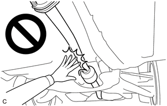
CAUTION:
To prevent burns, do not touch the engine, exhaust pipe or other high temperature components while the engine is hot.
HINT:
Use the same procedure for the No. 2 parking brake cable assembly and No. 3 parking brake cable assembly.
PROCEDURE
1. REMOVE FRONT SEAT ASSEMBLY LH
for Power Seat: Click here
.gif)
for Manual Seat: Click here
2. REMOVE FRONT SEAT ASSEMBLY RH
for Power Seat: Click here
for Manual Seat: Click here
3. REMOVE CONSOLE BOX ASSEMBLY
Click here
4. REMOVE REAR SEAT CUSHION ASSEMBLY
for Fold Down Seat Type: Click here
for Fixed Seat Type: Click here
5. REMOVE REAR SEAT CUSHION LOCK HOOK
for Fold Down Seat Type: Click here
for Fixed Seat Type: Click here
6. REMOVE FRONT DOOR SCUFF PLATE LH
Click here
7. REMOVE COWL SIDE TRIM SUB-ASSEMBLY LH
Click here
8. REMOVE NO. 1 INSTRUMENT PANEL UNDER COVER SUB-ASSEMBLY
Click here
9. DISCONNECT FRONT DOOR OPENING TRIM WEATHERSTRIP LH
Click here
10. REMOVE REAR DOOR SCUFF PLATE LH
Click here
11. DISCONNECT REAR DOOR OPENING TRIM WEATHERSTRIP LH
Click here
12. REMOVE LOWER CENTER PILLAR GARNISH LH
Click here
13. REMOVE FRONT DOOR SCUFF PLATE RH
HINT:
Use the same procedure as for the LH side.
14. REMOVE COWL SIDE TRIM SUB-ASSEMBLY RH
HINT:
Use the same procedure as for the LH side.
15. REMOVE NO. 2 INSTRUMENT PANEL UNDER COVER SUB-ASSEMBLY
Click here
16. DISCONNECT FRONT DOOR OPENING TRIM WEATHERSTRIP RH
HINT:
Use the same procedure as for the LH side.
17. REMOVE REAR DOOR SCUFF PLATE RH
HINT:
Use the same procedure as for the LH side.
18. DISCONNECT REAR DOOR OPENING TRIM WEATHERSTRIP RH
HINT:
Use the same procedure as for the LH side.
19. REMOVE LOWER CENTER PILLAR GARNISH RH
HINT:
Use the same procedure as for the LH side.
20. REMOVE ACCELERATOR PEDAL
Click here
21. DISCONNECT FRONT FLOOR CARPET ASSEMBLY
Click here
22. REMOVE NO. 1 CONSOLE BOX DUCT (for Dual Type)
Click here
23. SEPARATE NO. 1 PARKING BRAKE CABLE ASSEMBLY
Click here
24. REMOVE NO. 1 PARKING BRAKE PULL ROD SUB-ASSEMBLY (for Type A)
| (a) Separate the No. 3 parking brake cable assembly from the parking brake equalizer. |
|
(b) Separate the No. 2 parking brake cable assembly to remove the parking brake equalizer.
| (c) Slide the parking brake equalizer and rubber boot. |
|
(d) Remove the No. 1 parking brake pull rod sub-assembly from the parking brake equalizer.
25. REMOVE PARKING BRAKE EQUALIZER (for Type B)
| (a) Separate the No. 3 parking brake cable assembly from the parking brake equalizer. |
|
(b) Separate the No. 2 parking brake cable assembly to remove the parking brake equalizer.
26. REMOVE NO. 2 FLOOR UNDER COVER (for LH Side)
Click here
27. REMOVE NO. 1 FLOOR UNDER COVER (for RH Side)
Click here
28. REMOVE FRONT EXHAUST PIPE ASSEMBLY (TWC: Rear Catalyst)
Click here
29. REMOVE FRONT LOWER NO. 1 FLOOR HEAT INSULATOR
| (a) Remove the 2 nuts and front lower No. 1 floor heat insulator from the vehicle body. |
|
30. REMOVE PARKING BRAKE SHOE LEVER
Click here
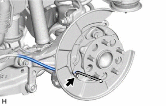
31. SEPARATE NO. 3 PARKING BRAKE CABLE ASSEMBLY
| (a) Remove the bolt and separate the No. 3 parking brake cable assembly from the backing plate. |
|
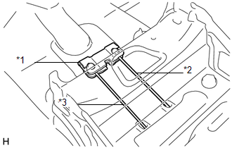
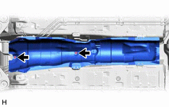
32. REMOVE NO. 3 PARKING BRAKE CABLE ASSEMBLY
(a) Remove the 3 bolts and nut, disengage the clamp and remove the No. 3 parking brake cable assembly.
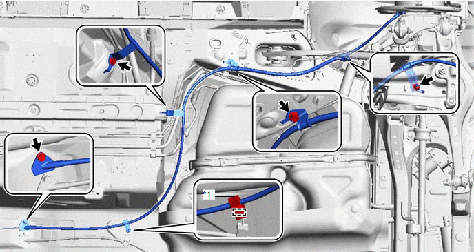
|
*1 | No. 1 Parking Brake Cable Clamp |
- | - |
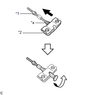
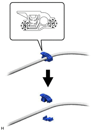
33. REMOVE NO. 1 PARKING BRAKE CABLE CLAMP
| (a) Disengage the 2 claws to remove the No. 1 parking brake cable clamp from the No. 3 parking brake cable assembly. |
|
READ NEXT:
 Installation
INSTALLATION CAUTION / NOTICE / HINT
HINT: Use the same procedure for the No. 2 parking brake cable assembly and No. 3 parking brake cable assembly. PROCEDURE
1. INSTALL NO. 1 PARKING BRAKE CABLE
Components
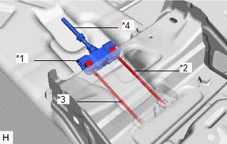
COMPONENTS ILLUSTRATION
*1 INSTRUMENT PANEL TO PEDAL BRACKET
*2 NO. 3 INSTRUMENT PANEL TO COWL BRACE SUB-ASSEMBLY
*3 PARKING BRAKE PEDAL ASSEMBLY
*4 NO. 1 PARKING
SEE MORE:
Parts Location
PARTS LOCATION ILLUSTRATION
*1 ECM
*2 ENGINE ROOM RELAY BLOCK AND JUNCTION BLOCK ASSEMBLY
- ST RELAY - EFI-MAIN NO. 1 FUSE - J/B-B FUSE - ETCS FUSE ILLUSTRATION
*A w/ Shift Paddle Switch
- -
*1 SHIFT LOCK CONTROL UNIT ASSEMBLY
- TRANSMISSIO
2gr-fks Coolant
ComponentsCOMPONENTS ILLUSTRATION
*1 RADIATOR CAP SUB-ASSEMBLY
*2 RADIATOR DRAIN COCK PLUG
*3 NO. 1 ENGINE UNDER COVER
- - ReplacementREPLACEMENT CAUTION / NOTICE / HINT
CAUTION: Do not remove the radiator cap sub-assembly, cylinder block drain cock plug or
