Toyota Camry (XV70): Removal
REMOVAL
CAUTION / NOTICE / HINT
The necessary procedures (adjustment, calibration, initialization, or registration) that must be performed after parts are removed and installed, or replaced during parking brake pedal assembly removal/installation are shown below.
Necessary Procedures After Parts Removed/Installed/Replaced|
Replaced Part or Performed Procedure |
Necessary Procedure | Effect/Inoperative Function when Necessary Procedure not Performed |
Link |
|---|---|---|---|
|
*1: When performing learning using the Techstream.
Click here | |||
|
Disconnect cable from negative battery terminal |
Perform steering sensor zero point calibration |
Lane Tracing Assist System |
|
|
Pre-collision system | |||
|
Parking Support Brake System*1 | |||
|
Memorize steering angle neutral point |
Parking assist monitor system |
| |
|
Panoramic view monitor system |
| ||
PROCEDURE
1. LOOSEN NO. 1 WIRE ADJUSTING NUT
| (a) Loosen the No. 1 wire adjusting nut. NOTICE: If the No. 1 wire adjusting nut has been removed from the No. 1 parking brake cable assembly, replace the No. 1 wire adjusting nut with a new one. |
|
2. REMOVE LOWER NO. 1 INSTRUMENT PANEL AIRBAG ASSEMBLY
Click here
.gif)
3. REMOVE NO. 3 INSTRUMENT PANEL TO COWL BRACE SUB-ASSEMBLY
Click here
4. REMOVE INSTRUMENT PANEL TO PEDAL BRACKET
| (a) Remove the bolt and nut. |
|
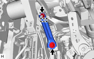
(b) Disengage the guide to remove the instrument panel to pedal bracket.
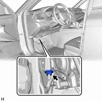
5. SEPARATE PARKING BRAKE PEDAL ASSEMBLY
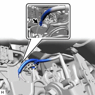
| (a) Disengage the clamp. |
|
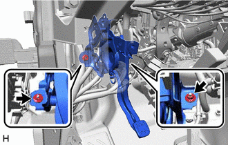
(b) Disconnect the parking brake switch connector.
| (c) Remove the 2 nuts, and separate the parking brake pedal assembly from the vehicle body. |
|
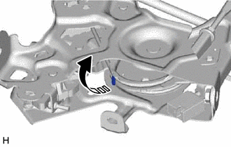
6. REMOVE PARKING BRAKE PEDAL ASSEMBLY
| (a) Pull up the parking brake pedal assembly claw. NOTICE: Do not damage the No. 1 parking brake cable assembly. |
|
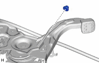
| (b) Remove the No. 1 wire adjusting nut from the No. 1 parking brake cable assembly. NOTICE: If the No. 1 wire adjusting nut has been removed from the No. 1 parking brake cable assembly, replace the No. 1 wire adjusting nut with a new one. |
|
| (c) Remove the clip from the No. 1 parking brake cable assembly. |
|
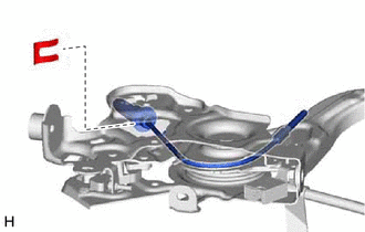
(d) Remove the parking brake pedal assembly from the No. 1 parking brake cable assembly.
READ NEXT:
 Disassembly
DISASSEMBLY PROCEDURE 1. REMOVE PARKING BRAKE SWITCH ASSEMBLY
Click here
2. REMOVE PARKING PEDAL PAD (a) Remove the parking pedal pad from the parking brake pedal assembly.
Reassembly
REASSEMBLY PROCEDURE 1. INSTALL PARKING PEDAL PAD
(a) Install the parking pedal pad to the parking brake pedal assembly.
2. INSTALL PARKING BRAKE SWITCH ASSEMBLY Click here
Installation
INSTALLATION PROCEDURE 1. INSTALL PARKING BRAKE PEDAL ASSEMBLY
(a) Pass the No. 1 parking brake cable assembly through the parking brake pedal assembly.
(b) Install a new clip to the No. 1 par
SEE MORE:
Components
COMPONENTS ILLUSTRATION
*A for Fold Down Seat Type
- -
*1 REAR CENTER SEAT OUTER BELT ASSEMBLY
*2 REAR SEAT CUSHION ASSEMBLY
*3 REAR SEAT CUSHION LOCK HOOK
*4 REAR SEAT INNER BELT ASSEMBLY RH
*5 WASHER
- -
Tight
ECM Communication (C124A00)
DESCRIPTION If the vehicle information stored by the skid control ECU (brake actuator assembly) does not match that sent from the ECM or a new skid control ECU (brake actuator assembly) is installed and the vehicle information has not been stored, this DTC is stored.
DTC No. Detection Item
