Toyota Camry (XV70): Removal
REMOVAL
CAUTION / NOTICE / HINT
The necessary procedures (adjustment, calibration, initialization, or registration) that must be performed after parts are removed and installed, or replaced during rear No. 1 differential mount cushion removal/installation are shown below.
Necessary Procedures After Parts Removed/Installed/Replaced|
Replaced Part or Performed Procedure |
Necessary Procedure | Effect/Inoperative Function when Necessary Procedure not Performed |
Link |
|---|---|---|---|
| Rear wheel alignment adjustment |
|
|
|
|
Suspension, tires, etc. (The vehicle height changes because of suspension or tire replacement) |
Rear television camera assembly optical axis (Back camera position setting) |
Parking assist monitor system |
|
| Panoramic view monitor system |
| |
|
Exhaust system parts | Inspection after repair |
|
|
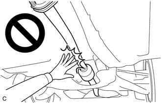
CAUTION:
To prevent burns, do not touch the engine, exhaust pipe or other high temperature components while the engine is hot.
PROCEDURE
1. REMOVE REAR DIFFERENTIAL CARRIER ASSEMBLY
Click here
.gif)
2. REMOVE REAR NO. 1 DIFFERENTIAL MOUNT CUSHION
(a) Using SST, remove the rear No. 1 differential mount cushion.
SST: 09316-12010
SST: 09570-24011
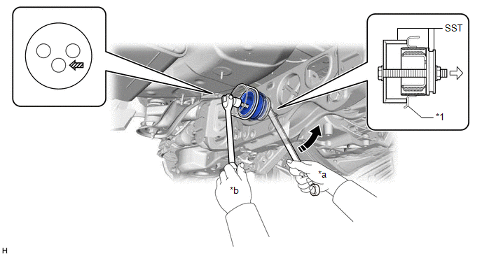
|
*1 | Rear Suspension Member Sub-assembly |
- | - |
|
*a | Turn |
*b | Hold |
 |
Turning Direction |
 |
Front of Vehicle |
 |
SST Bolt Position | - |
- |
NOTICE:
- Do not bring SST into contact with the rear suspension member sub-assembly.
- Before using SST, apply grease to SST bolt.
- Set SST in the correct direction.
- Do not tilt the SST bolt.
- Do not reuse the rear No. 1 differential mount cushion.
READ NEXT:
 Installation
INSTALLATION PROCEDURE 1. INSTALL REAR NO. 1 DIFFERENTIAL MOUNT CUSHION
(a) Using SST, install a new rear No. 1 differential mount cushion. SST: 09316-12010
SST: 09570-24011
*1 Rear Sus
Differential Oil
ComponentsCOMPONENTS ILLUSTRATION
*1 REAR DIFFERENTIAL FILLER PLUG
*2 REAR DIFFERENTIAL DRAIN PLUG
*3 GASKET
- -
N*m (kgf*cm, ft.*lbf): Specified t
Differential System
PrecautionPRECAUTION
Before disassembling the differential assembly, thoroughly clean it by removing any sand, mud or foreign matter. This will help prevent contamination during disassembly and r
SEE MORE:
ABS Warning Light does not Come ON
DESCRIPTION The skid control ECU (brake actuator assembly) controls the ABS warning light in the combination meter assembly via CAN communication. CAUTION / NOTICE / HINT
NOTICE: After replacing the skid control ECU (brake actuator assembly), perform acceleration sensor zero point calibration and
Drive Belt
PrecautionPRECAUTION
NOTICE:
Do not apply or add any oil or grease to the belt tensioner to prevent abnormal noises from the belt tensioner pulley, belt squealing, etc.
Do not allow oil or grease to adhere to the moving parts of the belt tensioner, as this may cause malfunctions.
