Toyota Camry (XV70): Removal
REMOVAL
CAUTION / NOTICE / HINT
The necessary procedures (adjustment, calibration, initialization, or registration) that must be performed after parts are removed and installed, or replaced during front axle hub sub-assembly removal/installation are shown below.
Necessary Procedures After Parts Removed/Installed/Replaced|
Replaced Part or Performed Procedure |
Necessary Procedure | Effect/Inoperative Function when Necessary Procedure not Performed |
Link |
|---|---|---|---|
| Front wheel alignment adjustment |
Perform system variant learning and acceleration sensor zero point calibration. |
| w/ Electric Parking Brake System:
w/o Electric Parking Brake System:
|
HINT:
- Use the same procedure for the RH side and LH side.
- The following procedure is for the LH side.
PROCEDURE
1. REMOVE FRONT WHEEL
Click here
.gif)
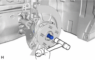
2. REMOVE FRONT AXLE SHAFT NUT
for A25A-FKS: Click here
for 2GR-FKS: Click here
3. SEPARATE FRONT SPEED SENSOR
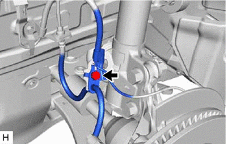
| (a) Remove the bolt and separate the front speed sensor and front flexible hose from the front shock absorber assembly. NOTICE: Be sure to separate the front speed sensor and front flexible hose from the front shock absorber assembly completely. |
|
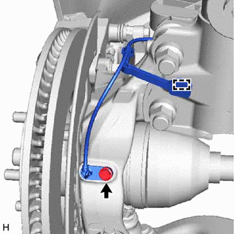
| (b) Remove the bolt, disengage the clamp and separate the front speed sensor from the front shock absorber assembly and steering knuckle. NOTICE:
|
|
4. SEPARATE TIE ROD ASSEMBLY
Click here
5. SEPARATE FRONT DISC BRAKE CALIPER ASSEMBLY
Click here
6. REMOVE FRONT DISC
except 2-Pot Caliper: Click here
for 2-Pot Caliper: Click here
7. SEPARATE FRONT LOWER NO. 1 SUSPENSION ARM SUB-ASSEMBLY
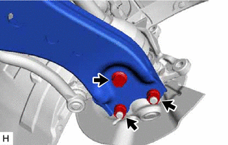
| (a) Remove the bolt and 2 nuts and separate the front lower No. 1 suspension arm sub-assembly from the front lower ball joint assembly. |
|
8. SEPARATE FRONT DRIVE SHAFT ASSEMBLY
| (a) Put matchmarks on the front drive shaft assembly and the front axle hub sub-assembly. |
|
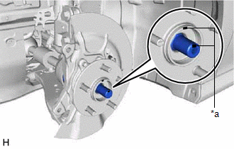
| (b) Using a plastic hammer, separate the front drive shaft assembly from the front axle assembly. NOTICE:
HINT: If it is difficult to separate the front drive shaft assembly from the front axle assembly, tap the end of the front drive shaft assembly using a brass bar and a hammer. |
|
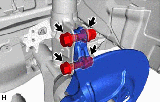
9. REMOVE FRONT AXLE ASSEMBLY
| (a) Remove the 2 bolts, 2 nuts and front axle assembly from the front shock absorber assembly. NOTICE: When removing the nuts, keep the bolts from rotating. |
|
10. REMOVE FRONT AXLE HUB SUB-ASSEMBLY
| (a) Secure the front axle assembly between aluminum plates in a vise. NOTICE: Do not overtighten the vise. |
|
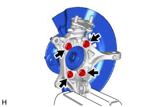
(b) Remove the 4 bolts, front axle hub sub-assembly and front disc brake dust cover from the steering knuckle.
NOTICE:
- Do not drop the front axle hub sub-assembly.
- Be careful not to damage the speed sensor rotor or contact surfaces.
- Do not allow foreign matter to contact the speed sensor rotor or contact surfaces.
READ NEXT:
 Installation
INSTALLATION CAUTION / NOTICE / HINT
HINT:
Use the same procedure for the RH side and LH side.
The following procedure is for the LH side.
PROCEDURE 1. INSTALL FRONT AXLE HUB SUB-ASSEMBL
Front Axle Hub Bolt
ComponentsCOMPONENTS ILLUSTRATION
*A except 2-Pod Caliper
*B for 2-Pod Caliper
*1 FRONT AXLE HUB BOLT
*2 FRONT DISC
*3 FRONT DISC BRAKE CALIPER ASSEMBLY
SEE MORE:
Diagnostic Trouble Code Chart
DIAGNOSTIC TROUBLE CODE CHART Vehicle Stability Control System
DTC No. Detection Item
Link C00631C
Yaw Rate Sensor Circuit Voltage Out of Range
C00631F Yaw Rate Sensor Circuit Intermittent
C006396 Yaw Rate Sensor Component Internal Failure
Installation
INSTALLATION PROCEDURE 1. INSTALL HEATED OXYGEN SENSOR (for Bank 2)
HINT: Perform "Inspection After Repair" after replacing the heated oxygen sensor.
Click here
(a) Using SST, install the heated oxygen sensor to the front exhaust pipe assembly.
SST: 09224-00012 Torque: Specified
