Toyota Camry (XV70): Removal
REMOVAL
CAUTION / NOTICE / HINT
The necessary procedures (adjustment, calibration, initialization, or registration) that must be performed after parts are removed, installed, or replaced during automatic transaxle assembly removal/installation are shown below.
Necessary Procedure After Parts Removed/Installed/Replaced|
Replaced Part or Performed Procedure |
Necessary Procedure | Effect/Inoperative Function when Necessary Procedure not Performed |
Link |
|---|---|---|---|
| *1: When the ECM is replaced with a new one, reset memory is unnecessary. | |||
| Battery terminal is disconnected/reconnected |
Perform steering sensor zero point calibration |
Lane Tracing Assist System |
|
|
Pre-collision system | |||
|
Memorize steering angle neutral point |
Parking assist monitor system |
| |
|
Panoramic view monitor system |
| ||
|
Replacement of ECM | Vehicle Identification Number (VIN) registration |
MIL comes on |
|
|
ECU communication ID registration (Immobiliser system) |
Engine start function |
| |
| Inspection After Repair |
|
|
|
Replacement of automatic transaxle assembly |
|
| for Initialization for Registration |
|
Replacement of ECM (If possible, read the transaxle compensation code from the previous ECM) |
| ||
| Replacement of ECM (If impossible, read the transaxle compensation code from the previous ECM) |
| ||
| Replacement of ECM |
Code registration |
|
|
|
Replacement of automatic transaxle fluid |
ATF thermal degradation estimate reset |
The value of the Data List item "ATF Thermal Degradation Estimate" is not estimated correctly. |
|
|
Suspension, tires, etc. (The vehicle height changes because of suspension or tire replacement) |
Rear television camera assembly optical axis (Back camera position setting) |
Parking assist monitor system |
for Initialization for Calibration |
|
Replacement of front bumper assembly |
Front television camera view adjustment |
Panoramic view monitor system |
for Initialization for Calibration |
|
Suspension, tires, etc. (The vehicle height changes because of suspension or tire replacement) |
| ||
| Front wheel alignment adjustment |
|
|
|
CAUTION:
- The engine assembly with transaxle is very heavy. Be sure to follow the procedure described in the repair manual, or the engine lifter may suddenly drop or the engine assembly with transaxle may fall off the engine lifter.
.png)
*a
An Object Exceeding Weight Limit of Engine Lifter
- To prevent burns, do not touch the engine, exhaust manifold or other high temperature components while the engine is hot.
.png)
- The automatic transaxle assembly is very heavy. Be sure to follow the procedure described in the repair manual, or the transmission jack may suddenly drop.
.png)
*a
An Object Exceeding Weight Limit of Transmission Jack
PROCEDURE
1. REMOVE FLYWHEEL HOUSING UNDER COVER
Click here .gif)
2. REMOVE DRIVE PLATE AND TORQUE CONVERTER ASSEMBLY SETTING BOLT
| (a) Turn the crankshaft to gain access to the 6 drive plate and torque converter assembly setting bolts and remove each drive plate and torque converter assembly setting bolt while holding the crankshaft pulley bolt with a wrench. HINT: There will be one black colored drive plate and torque converter assembly setting bolt. |
|
3. REMOVE ENGINE ASSEMBLY WITH TRANSAXLE
Click here
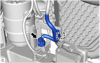
4. DISCONNECT VACUUM HOSE
| (a) Disconnect the vacuum hose from the rear engine mounting insulator. |
|
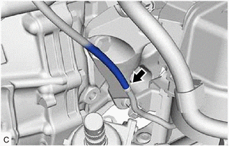
| (b) Disconnect the vacuum hose from the intake air surge tank assembly. |
|
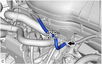
(c) Disengage the clamp to disconnect the vacuum hose from the hose clamp.
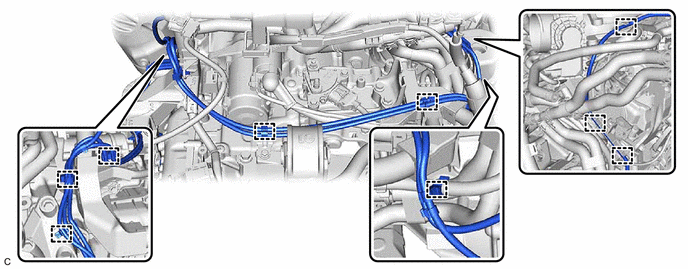
(d) Disengage the 9 clamps to disconnect the vacuum hose from the automatic transaxle assembly.
5. REMOVE STARTER ASSEMBLY
Click here
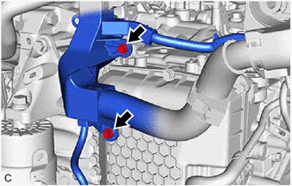
6. REMOVE BREATHER PLUG HOSE
| (a) Disengage the 3 hose clamps to disconnect the breather plug hose. |
|
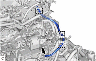
(b) Using a screwdriver with its tip wrapped with protective tape, remove the breather plug hose from the No. 1 breather plug (ATM).
NOTICE:
Be careful not to damage the No. 1 breather plug (ATM).
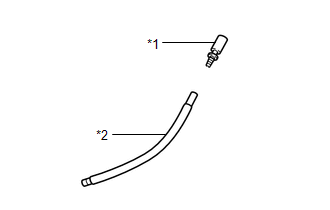
| (c) Remove the breather plug sub-assembly from the breather plug hose. NOTICE: Be careful not to damage the breather plug sub-assembly. |
|
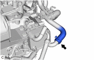
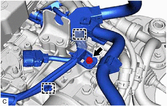
7. DISCONNECT NO. 1 WATER BY-PASS HOSE
| (a) Disengage the 2 clamps to remove the transmission breather clamp. |
|
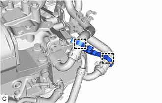
| (b) Slide the clip and disconnect the No. 1 water by-pass hose from the transmission oil cooler. HINT: Use a container to catch any coolant which flows out of the No. 1 water by-pass hose and transmission oil cooler. |
|
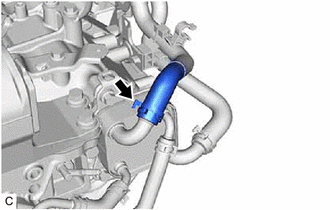
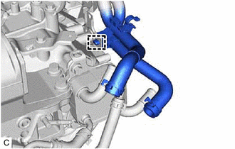
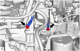
8. DISCONNECT WATER BY-PASS HOSE ASSEMBLY
| (a) Slide the clip and disconnect the water by-pass hose assembly from the transmission oil cooler. HINT: Use a container to catch any coolant which flows out of the water by-pass hose assembly and transmission oil cooler. |
|
| (b) Disengage the clamp to disconnect the water by-pass hose assembly from the automatic transaxle assembly. |
|
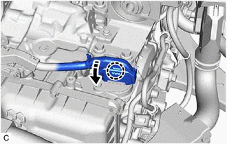
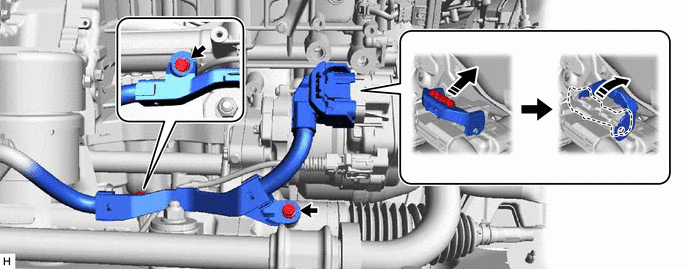
9. DISCONNECT WIRE HARNESS
| (a) Disengage the claw, rotate the lever and disconnect the transmission wire connector. |
|
| (b) Disconnect the park/neutral position switch assembly connector. |
|
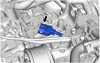
| (c) Disengage the wire harness clamp and disconnect the vacuum switching valve (for active control engine mount system) connector. |
|
| (d) Remove the 2 bolts. |
|
| (e) Remove the bolt. |
|
(f) Disengage the 2 wire harness clamps to disconnect the wire harness.
| (g) Remove the 2 bolts. |
|
(h) Disconnect the rack and pinion power steering gear assembly connector.
HINT:
Release the lock before rotating the lock lever.
(i) Remove the 2 bolts to disconnect the wire harness.
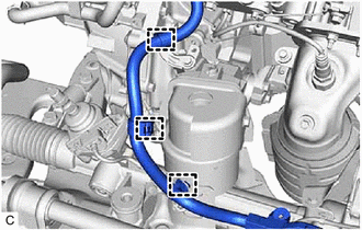
| (j) Disengage the 3 wire harness clamps to disconnect the wire harness from the automatic transaxle assembly. |
|
10. INSTALL ENGINE HANGERS
Click here
11. REMOVE FRONT FRAME ASSEMBLY
Click here
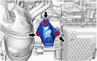
12. REMOVE FRONT ENGINE MOUNTING BRACKET
| (a) Remove the 3 bolts and front engine mounting bracket from the transaxle housing. |
|
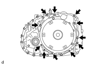
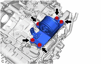
13. REMOVE AUTOMATIC TRANSAXLE ASSEMBLY
(a) Support the automatic transaxle assembly with a transmission jack.
NOTICE:
Secure the automatic transaxle assembly to the transmission jack using a suitable adapter, such as a rope or attachment.
| (b) Remove the 11 bolts and automatic transaxle assembly. NOTICE: To prevent damage to the knock pins, do not pry between the automatic transaxle assembly and engine assembly. |
|
14. REMOVE REAR NO. 2 ENGINE MOUNTING INSULATOR
| (a) Remove the 5 bolts and rear No. 2 engine mounting insulator from the automatic transaxle case sub-assembly. |
|
15. REMOVE REAR ENGINE MOUNTING INSULATOR
Click here
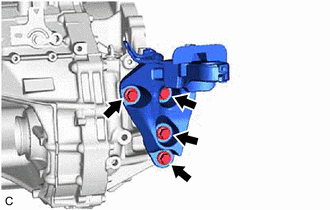
16. REMOVE REAR ENGINE MOUNTING BRACKET SUB-ASSEMBLY
| (a) Remove the 4 bolts and rear engine mounting bracket sub-assembly from the transaxle housing. |
|
17. DISCONNECT OUTLET NO. 1 OIL COOLER HOSE
Click here
18. DISCONNECT INLET NO. 1 OIL COOLER HOSE
Click here
19. REMOVE NO. 1 OIL COOLER TUBE SUB-ASSEMBLY WITHOUT HOSE
Click here
20. REMOVE TRANSMISSION OIL COOLER
Click here
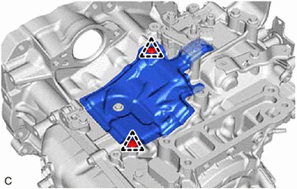
21. REMOVE AUTOMATIC TRANSMISSION CASE COVER
| (a) Remove the 2 clips and automatic transmission case cover from the automatic transaxle case sub-assembly. |
|
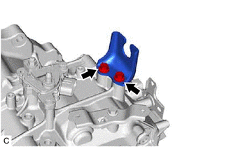
22. REMOVE NO. 1 TRANSMISSION CONTROL CABLE BRACKET
| (a) Remove the 2 bolts and No. 1 transmission control cable bracket from the automatic transaxle case sub-assembly. |
|
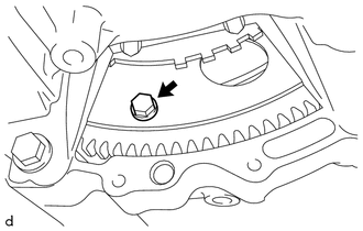
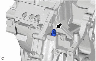
23. REMOVE TRANSMISSION CASE PLUG ASSEMBLY
| (a) Remove the transmission case plug assembly from the transaxle housing. |
|
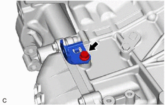
24. REMOVE WIRE HARNESS CLAMP BRACKET
| (a) Remove the bolt and wire harness clamp bracket from the automatic transaxle case sub-assembly. |
|
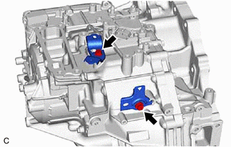
| (b) Remove the 2 bolts and 2 wire harness clamp brackets from the automatic transaxle case sub-assembly. |
|
25. REMOVE TORQUE CONVERTER ASSEMBLY
(a) Remove the torque converter assembly from the automatic transaxle assembly.
26. INSPECT TORQUE CONVERTER ASSEMBLY
Click here
27. INSPECT DRIVE PLATE AND RING GEAR SUB-ASSEMBLY
Click here
READ NEXT:
 Installation
INSTALLATION CAUTION / NOTICE / HINT
CAUTION: The engine assembly with transaxle is very heavy. Be sure to follow the procedure described in the repair manual, or the engine lifter may suddenly drop
Components
COMPONENTS ILLUSTRATION
*1 REAR ENGINE UNDER COVER LH
*2 FRONT FENDER APRON SEAL LH
*3 NO. 1 ENGINE UNDER COVER
*4 FRONT WHEEL OPENING EXTENSION PAD LH
*5
SEE MORE:
Pressure Control Solenoid "A" Circuit Short to Battery (P074512)
DESCRIPTION Changing gears is performed by the ECM turning the solenoid (SL1, SL2, SL3, SL4, SL5 and SL6) valves on and off.
If an open or short occurs in any of the solenoid valve circuits, the ECM controls the remaining normal solenoid valves to allow the vehicle to be driven. If all of the sole
Right Rear Wheel Speed Sensor Signal Stuck High (C051224)
DESCRIPTION Refer to DTC C051212 Click here
DTC No. Detection Item
DTC Detection Condition Trouble Area
C051224 Right Rear Wheel Speed Sensor Signal Stuck High
The speed sensor signal is not within the specified range for 5 seconds or more.
Rear speed se
