Toyota Camry (XV70): Removal
REMOVAL
CAUTION / NOTICE / HINT
The necessary procedures (adjustment, calibration, initialization, or registration) that must be performed after parts are removed and installed, or replaced during rear engine mounting insulator removal/installation are shown below.
Necessary Procedures After Parts Removed/Installed/Replaced|
Replaced Part or Performed Procedure |
Necessary Procedure | Effect/Inoperative Function when Necessary Procedure not Performed |
Link |
|---|---|---|---|
| *1: When the ECM is replaced with a new one, reset memory is unnecessary. | |||
| Battery terminal is disconnected/reconnected |
Perform steering sensor zero point calibration |
Lane Tracing Assist System |
|
|
Pre-collision System | |||
|
Memorize steering angle neutral point |
Parking Assist Monitor System |
| |
|
Panoramic View Monitor System |
| ||
|
Replacement of ECM | Vehicle Identification Number (VIN) registration |
MIL comes on |
|
|
ECU communication ID registration (Immobiliser system) |
Engine start function |
| |
|
Gas leak from exhaust system is repaired |
Inspection After Repair |
|
|
|
Replacement of ECM (If possible, read the transaxle compensation code from the previous ECM) |
|
|
|
|
Replacement of ECM (If impossible, read the transaxle compensation code from the previous ECM) |
| ||
| Replacement of automatic transaxle fluid |
ATF thermal degradation estimate reset |
The value of the Data List item "ATF Thermal Degradation Estimate" is not estimated correctly. |
|
|
Replacement of ECM | Code registration |
|
|
|
Suspension, tires, etc. (The vehicle height changes because of suspension or tire replacement) |
Rear television camera assembly optical axis (Back camera position setting) |
Parking assist monitor system |
|
|
Replacement of front bumper assembly |
Front television camera view adjustment |
Panoramic view monitor system |
|
|
Suspension, tires, etc. (The vehicle height changes because of suspension or tire replacement) |
| ||
| Front wheel alignment adjustment |
|
|
|
PROCEDURE
1. REMOVE FRONT FRAME ASSEMBLY
Click here
.gif)
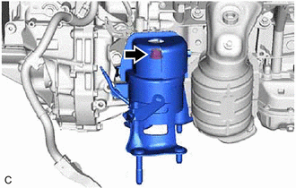
2. REMOVE REAR ENGINE MOUNTING INSULATOR
| (a) Remove the bolt and rear engine mounting insulator from the rear engine mounting bracket. |
|
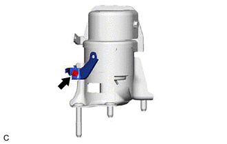
| (b) Remove the bolt and wire harness clamp bracket from the rear engine mounting insulator. |
|
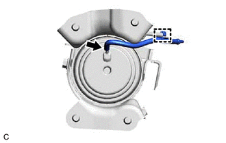
| (c) Disengage the clamp and remove the vacuum hose from the rear engine mounting insulator. |
|
READ NEXT:
 Installation
INSTALLATION PROCEDURE 1. INSTALL REAR ENGINE MOUNTING INSULATOR
(a) Engage the clamp and install the vacuum hose to the rear engine mounting insulator.
(b) Install the wire harness clamp bracket
Components
COMPONENTS ILLUSTRATION
*1 V-BANK COVER SUB-ASSEMBLY
*2 AIR FUEL RATIO SENSOR (for Bank 1)
*3 AIR FUEL RATIO SENSOR (for Bank 2)
- -
N*m (kgf*cm, f
SEE MORE:
Diagnostic Trouble Code Chart
DIAGNOSTIC TROUBLE CODE CHART SFI System
DTC No. Detection Item
MIL Memory
Note Link
P001013 A Camshaft Position Actuator Bank 1 Circuit Open
Comes on DTC stored
SAE Code: P0010
P001100 Camshaft Position "A" - Timing Over-Advanced or S
Left Front Wheel Speed Sensor Circuit Intermittent (C05001F)
DESCRIPTION Refer to DTC C050012 Click here
DTC No. Detection Item
DTC Detection Condition Trouble Area
C05001F Left Front Wheel Speed Sensor Circuit Intermittent
The speed sensor signal is excessively noisy.
The calculated change in wheel speed is more
