Toyota Camry (XV70): Replacement
REPLACEMENT
PROCEDURE
1. REPLACE STRAIGHT PIN
NOTICE:
If a straight pin is deformed, replace it.
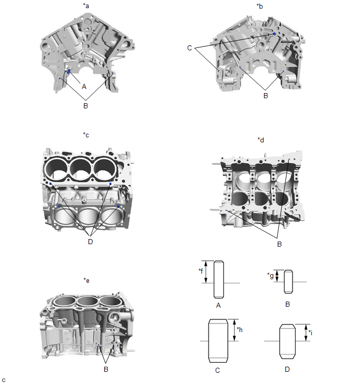
(a) Using a plastic hammer, tap in new straight pins to the cylinder block sub-assembly.
|
*a | Front Side |
*b | Rear Side |
|
*c | Top Side |
*d | Bottom Side |
|
*e | RH Side |
*f | 23 mm (0.906 in.) |
|
*g | 6 mm (0.236 in.) |
*h | 11 mm (0.433 in.) |
|
*i | 9 mm (0.354 in.) |
- | - |
Standard Protrusion Height:
|
Item | Specified Condition |
|---|---|
|
Pin (A) | 23 mm (0.906 in.) |
|
Pin (B) | 6 mm (0.236 in.) |
|
Pin (C) | 11 mm (0.433 in.) |
|
Pin (D) | 9 mm (0.354 in.) |
2. REPLACE STUD BOLT
NOTICE:
If a stud bolt is deformed or its threads are damaged, replace it.
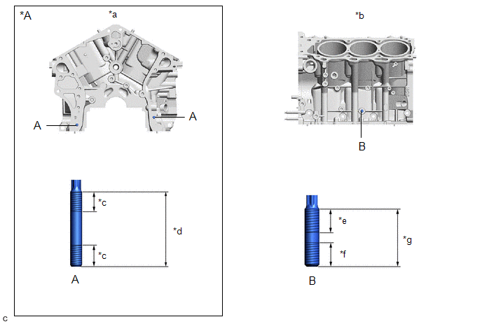
(a) Using E8 and E10 "TORX" socket wrenches, install the stud bolts to the cylinder block sub-assembly.
|
*A | w/ Stud Bolt |
- | - |
|
*a | Front Side |
*b | LH Side |
|
*c | 12 mm (0.472 in.) |
*d | 52 mm (2.05 in.) |
|
*e | 23 mm (0.906 in.) |
*f | 15 mm (0.591 in.) |
|
*g | 40 mm (1.57 in.) |
- | - |
Torque:
10 N·m {102 kgf·cm, 7 ft·lbf}
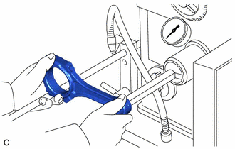
3. REPLACE CONNECTING ROD SMALL END BUSH
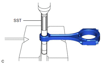
| (a) Using SST and a press, press out the connecting rod small end bush. SST: 09222-30010 |
|
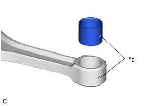
| (b) Align the oil hole of a new connecting rod small end bush with the oil hole of the connecting rod. |
|
| (c) Using SST and a press, push in the connecting rod small end bush. SST: 09222-30010 |
|
| (d) Using a pin hole grinder, hone the connecting rod small end bush to obtain the standard oil clearance between the connecting rod small end bush and piston pin. Standard Oil Clearance: 0.005 to 0.011 mm (0.000197 to 0.000433 in.) |
|
(e) Coat the piston pin with engine oil, and push it into the connecting rod with your thumb.
HINT:
Check that the piston pin fits at a normal room temperature.
READ NEXT:
 Reassembly
REASSEMBLY PROCEDURE 1. INSTALL NO. 1 OIL NOZZLE SUB-ASSEMBLY
(a) Using a 5 mm hexagon socket wrench, install the 3 No. 1 oil nozzle sub-assemblies to the cylinder block sub-assembly with the 3
Precaution
PRECAUTION
HINT:
Any digits beyond the 1/100 mm (1/1000 in.) place for standard, minimum and maximum values should be used as a reference only.
When both standard and maximum or minimum val
SEE MORE:
Inspection
INSPECTION PROCEDURE 1. INSPECT KNOCK CONTROL SENSOR
(a) Measure the resistance according to the value(s) in the table below.
Standard Resistance:
Tester Connection Condition
Specified Condition
1 - 2 25°C (77°F)
120 to 280 kΩ If the result is not
Electric parking brake
A mode can be selected from the following modes.
Automatic mode
The parking brake is set or released automatically according to the
shift lever operation.
Even when in automatic mode, the parking brake can be set and
released manually.
Turns automatic mode on
(while the vehicle is stopp
