Toyota Camry (XV70): Right Rear Wheel Speed Sensor Circuit Short to Ground or Open (C051214)
DESCRIPTION
Refer to DTC C051212
Click here
.gif)
|
DTC No. | Detection Item |
DTC Detection Condition | Trouble Area |
|---|---|---|---|
|
C051214 | Right Rear Wheel Speed Sensor Circuit Short to Ground or Open |
A short or open circuit is detected in the speed sensor signal circuit for 0.12 seconds or more. |
|
|
Vehicle Condition | |||
|---|---|---|---|
|
Pattern 1 | Pattern 2 | ||
|
Diagnosis Condition | - |
- | - |
|
Malfunction Status | An open circuit is detected in the speed sensor signal circuit. |
○ | - |
|
A short circuit is detected in the speed sensor signal circuit. |
- | ○ | |
|
Detection Time | 0.12 seconds or more. |
0.12 seconds or more. | |
|
Number of Trips | 1 trip |
1 trip | |
HINT:
DTC will be output when conditions for either of the patterns in the table above are met.
WIRING DIAGRAM
Refer to DTC C051212.
Click here
CAUTION / NOTICE / HINT
NOTICE:
- After replacing the skid control ECU (brake actuator assembly), perform acceleration sensor zero point calibration and system information memorization.
Click here
- After replacing or removing and installing a speed sensor, perform Dealer Mode (Signal Check) inspection to confirm that the speed sensors are operating correctly.
Click here
PROCEDURE
|
1. | CHECK HARNESS AND CONNECTOR (SENSOR GROUND CIRCUIT) |
| (a) Make sure that there is no looseness at the locking part and the connecting part of the connectors. OK: The connector is securely connected. |
|
.png)
(b) Disconnect the f1 rear speed sensor RH (rear axle hub and bearing assembly RH) connector.
(c) Check both the connector case and the terminals for deformation and corrosion.
OK:
No deformation or corrosion.
(d) Turn the ignition switch to ON.
(e) Measure the voltage according to the value(s) in the table below.
Standard Voltage:
|
Tester Connection | Condition |
Specified Condition |
|---|---|---|
|
f1-2 (RR+) - f1-1 (RR-) |
Ignition switch ON | 11 to 14 V |
| NG | .gif) | GO TO STEP 4 |
|
.gif)
| 2. |
INSPECT SKID CONTROL SENSOR WIRE RH |
| (a) Make sure that there is no looseness at the locking part and the connecting part of the connectors. OK: The connector is securely connected. |
|
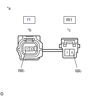
(b) Disconnect the f1 skid control sensor wire RH connector.
(c) Disconnect the fR1 skid control sensor wire RH connector.
(d) Check both the connector case and the terminals for deformation and corrosion.
OK:
No deformation or corrosion.
(e) Measure the resistance according to the value(s) in the table below.
Standard Resistance:
|
Tester Connection | Condition |
Specified Condition |
|---|---|---|
|
f1-1 (RR-) or fR1-2 (RR-) - Body ground and other terminals |
Always | 10 kΩ or higher |
| NG | | REPLACE SKID CONTROL SENSOR WIRE RH |
|
| 3. |
CHECK HARNESS AND CONNECTOR (SKID CONTROL SENSOR WIRE RH - BRAKE ACTUATOR ASSEMBLY) |
(a) Make sure that there is no looseness at the locking part and the connecting part of the connectors.
OK:
The connector is securely connected.
(b) Disconnect the A33 skid control ECU (brake actuator assembly) connector.
(c) Disconnect the fR1 skid control sensor wire RH connector.
(d) Check both the connector case and the terminals for deformation and corrosion.
OK:
No deformation or corrosion.
(e) Measure the resistance according to the value(s) in the table below.
Standard Resistance:
|
Tester Connection | Condition |
Specified Condition |
|---|---|---|
|
fR1-2 (RR-) or A33-29 (RR-) - Body ground |
Always | 10 kΩ or higher |
| OK | | REPLACE REAR AXLE HUB AND BEARING ASSEMBLY RH |
| NG | | REPAIR OR REPLACE HARNESS OR CONNECTOR |
| 4. |
INSPECT SKID CONTROL SENSOR WIRE RH |
| (a) Make sure that there is no looseness at the locking part and the connecting part of the connectors. OK: The connector is securely connected. |
|
(b) Disconnect the f1 skid control sensor wire RH connector.
(c) Disconnect the fR1 skid control sensor wire RH connector.
(d) Check both the connector case and the terminals for deformation and corrosion.
OK:
No deformation or corrosion.
(e) Measure the resistance according to the value(s) in the table below.
Standard Resistance:
|
Tester Connection | Condition |
Specified Condition |
|---|---|---|
|
f1-1 (RR-) - fR1-2 (RR-) |
Always | Below 1 Ω |
| NG | | REPLACE SKID CONTROL SENSOR WIRE RH |
|
| 5. |
CHECK HARNESS AND CONNECTOR (SKID CONTROL SENSOR WIRE RH - BRAKE ACTUATOR ASSEMBLY) |
(a) Make sure that there is no looseness at the locking part and the connecting part of the connectors.
OK:
The connector is securely connected.
(b) Disconnect the A33 skid control ECU (brake actuator assembly) connector.
(c) Disconnect the fR1 skid control sensor wire RH connector.
(d) Check both the connector case and the terminals for deformation and corrosion.
OK:
No deformation or corrosion.
(e) Measure the resistance according to the value(s) in the table below.
Standard Resistance:
|
Tester Connection | Condition |
Specified Condition |
|---|---|---|
|
fR1-2 (RR-) - A33-29 (RR-) |
Always | Below 1 Ω |
| OK | | REPLACE BRAKE ACTUATOR ASSEMBLY |
| NG | | REPAIR OR REPLACE HARNESS OR CONNECTOR |
READ NEXT:
 Right Rear Wheel Speed Sensor Circuit Voltage Out of Range (C05121C)
DESCRIPTION Refer to DTC C051212 Click here
DTC No. Detection Item
DTC Detection Condition Trouble Area
C05121C Right Rear Wheel Speed Sensor Circuit Voltage Out of Range
Right Rear Wheel Speed Sensor Circuit Intermittent (C05121F)
DESCRIPTION Refer to DTC C051212 Click here
DTC No. Detection Item
DTC Detection Condition Trouble Area
C05121F Right Rear Wheel Speed Sensor Circuit Intermittent
Right Rear Wheel Speed Sensor Signal Stuck Low (C051223)
DESCRIPTION Refer to DTC C051212 Click here
DTC No. Detection Item
DTC Detection Condition Trouble Area
C051223 Right Rear Wheel Speed Sensor Signal Stuck Low
W
SEE MORE:
SRS airbag system components
Front impact sensors
Front passenger occupant
classification system (ECU
and sensors)
Knee airbags
Side impact sensors (front
doors)
Side impact sensors (front)
Front passenger airbag
Front side airbags
Curtain shield airbags
Rear side airbags
"AIRBAG ON" and "AIRBAG
O
Right Rear Wheel ABS Hold Solenoid Control Circuit Short to Battery (C12E712,...,C12F249)
DESCRIPTION The ABS solenoid relay and solenoid valves are built into the brake actuator assembly.
The rear solenoid valve RH controls the brake fluid pressure of the rear wheel cylinder RH of the vehicle.
When this DTC is stored, the fail-safe function operates and the ABS solenoid relay is tur
