Toyota Camry (XV70): Terminals Of Ecm
TERMINALS OF ECM
ECM
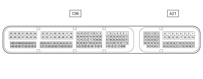
HINT:
The standard voltage and resistance of each ECM terminal is shown in the table below.
In the table, first follow the information under "Condition". Look under "Terminal No. (Symbol)" for the terminals to be inspected. The standard voltage or resistance between the terminals is shown under "Specified Condition".
Use the illustration above as a reference for the ECM terminals.
|
Terminal No. (Symbol) | Wiring Color |
Terminal Description | Condition |
Specified Condition |
|---|---|---|---|---|
|
A21-1 (BATT) - C96-53 (E1) |
R - W-B | Battery (for measuring battery voltage and for ECM memory) |
Always | 11 to 14 V |
|
A21-2 (+B) - C96-53 (E1) |
L - W-B | Power source of ECM |
Engine switch on (IG) |
11 to 14 V |
|
A21-3 (+B2) - C96-53 (E1) |
L - W-B | Power source of ECM |
Engine switch on (IG) |
11 to 14 V |
|
A21-8 (+BM) - C96-53 (E1) |
G - W-B | Power source of ECM |
Always | 11 to 14 V |
|
A21-13 (CANH) - C96-53 (E1) |
B - W-B | CAN communication line |
Engine switch on (IG) |
Pulse generation |
|
A21-17 (S) - C96-53 (E1) |
GR - W-B | S shift position switch signal |
Engine switch on (IG) and shift lever in S |
11 to 14 V |
| Engine switch on (IG) and shift lever not in S |
Below 1 V | |||
|
A21-26 (CANL) - C96-53 (E1) |
W - W-B | CAN communication line |
Engine switch on (IG) |
Pulse generation |
|
A21-27 (STP) - C96-53 (E1) |
SB - W-B | Stop light switch signal |
Brake pedal depressed |
7.5 to 14 V |
|
Brake pedal released |
Below 1 V | |||
|
A21-37 (SFTD) - C96-53 (E1) |
W - W-B | Down-shift switch signal |
Engine switch on (IG) |
11 to 14 V |
| Engine switch on (IG) and shift lever held in "-" (Down shift) |
Below 1 V | |||
| Engine switch on (IG) and "-" (Down shift) shift paddle switch operated |
Below 1 V | |||
|
A21-38 (SFTU) - C96-53 (E1) |
G - W-B | Up-shift switch signal |
Engine switch on (IG) |
11 to 14 V |
| Engine switch on (IG) and shift lever held in "+" (Up shift) |
Below 1 V | |||
| Engine switch on (IG) and "+" (Up shift) shift paddle switch operated |
Below 1 V | |||
|
A21-39 (SPD) - C96-53 (E1) |
L - W-B | Vehicle speed signal from combination meter assembly |
Driving at 20 km/h (12 mph) |
Pulse generation |
|
A21-40 (SPCN) - C96-53 (E1) |
V - W-B | Combination switch (NORMAL) signal |
Engine switch on (IG) and combination switch (NORMAL) being pushed and held |
Below 1.5 V |
|
Engine switch on (IG) and combination switch (NORMAL) not pushed |
11 to 14 V | |||
|
A21-43 (STA) - C96-53 (E1) |
G - W-B | Starter signal |
Cranking (shift lever in P or N, engine switch on (START)) |
11 to 14 V |
| Engine switch on (IG) and shift lever in P or N |
Below 2 V | |||
|
A21-55 (PWMS) - C96-53 (E1) |
LG - W-B | Combination switch (SPORT) signal |
Engine switch on (IG) and combination switch (SPORT) being pushed and held |
Below 1.5 V |
|
Engine switch on (IG) and combination switch (SPORT) not pushed |
11 to 14 V | |||
| C96-6 (SL3+) - C96-7 (SL3-) |
L - R | Solenoid (SL3) valve signal |
3rd, 7th or Reverse gear |
Pulse generation |
|
C96-10 (SL5+) - C96-11 (SL5-) |
W - R | Solenoid (SL5) valve signal |
2nd or 8th gear | Pulse generation |
|
C96-12 (SL1+) - C96-13 (SL1-) |
G - BR | Solenoid (SL1) valve signal |
1st, 2nd, 3rd, 4th or 5th gear |
Pulse generation |
|
C96-14 (SL4+) - C96-15 (SL4-) |
LG - R | Solenoid (SL4) valve signal |
4th or 6th gear | Pulse generation |
|
C96-31 (SL2+) - C96-1 (SL2-) |
LG - P | Solenoid (SL2) valve signal |
5th, 6th, 7th or 8th gear |
Pulse generation |
| C96-32 (SL6+) - C96-33 (SL6-) |
GR - LG | Solenoid (SL6) valve signal |
1st or Reverse gear | Pulse generation |
|
C96-53 (E1) - Body ground |
W-B - Body ground | Ground |
Always | Below 1 Ω |
|
C96-62 (SL) - C96-53 (E1) |
W - W-B | Solenoid (SL) valve signal |
| 11 to 14 V |
|
C96-67 (SLT+) - C96-37 (SLT-) |
G - B | Solenoid (SLT) valve signal |
Engine idling | Pulse generation |
|
C96-72 (NCO) - C96-53 (E1) |
L - W-B | Transmission Revolution Sensor (NC) signal |
Vehicle being driven |
Pulse generation |
|
C96-73 (NCB) - C96-53 (E1) |
G - W-B | Power source for sensor (specific voltage) | Engine switch on (IG) |
11 to 14 V |
|
C96-74 (NTO) - C96-53 (E1) |
B - W-B | Transmission Revolution Sensor (NT) signal |
Engine idling (shift lever in P or N) |
Pulse generation |
|
C96-75 (NTB) - C96-53 (E1) |
R - W-B | Power source for sensor (specific voltage) | Engine switch on (IG) |
11 to 14 V |
|
C96-76 (SLU+) - C96-61 (SLU-) |
L - B | Solenoid (SLU) valve signal |
Lock-up ON | Pulse generation |
|
C96-86 (THO1) - C96-133 (ETHW) |
W - BR | ATF temperature sensor signal |
ATF temperature 115 |
READ NEXT:
 Diagnosis System
DIAGNOSIS SYSTEM DESCRIPTION (a) When troubleshooting On-Board Diagnostic (OBD II) vehicles, an OBD II scan tool (complying with SAE J1978) must be connected to the vehicle. Various data output from t
Dtc Check / Clear
DTC CHECK / CLEAR NOTICE: When the diagnosis system is changed from normal mode to check mode or vice versa, all DTCs and freeze frame data recorded in normal mode are cleared. Before changing modes,
Check Mode Procedure
CHECK MODE PROCEDURE DESCRIPTION (a) Check mode has a higher sensitivity to malfunctions and can detect malfunctions that normal mode cannot detect. Check mode can also detect all of the malfunctions
SEE MORE:
Dtc Check / Clear
DTC CHECK / CLEAR CHECK FOR DTC (a) Check for DTCs (Test Failed / Pending / Confirmed). Body Electrical > Road Sign Assist > Trouble Codes
Techstream Display Description
Test Failed Shows the malfunction judgment results during the current trip.
Pending Shows the ma
Removal
REMOVAL CAUTION / NOTICE / HINT
The necessary procedures (adjustment, calibration, initialization, or registration) that must be performed after parts are removed and installed, or replaced during rear engine mounting insulator removal/installation are shown below. Necessary Procedures After Parts
