Toyota Camry (XV70): AV Signal Stoppage (Low Battery Voltage) (B158F)
DESCRIPTION
This DTC is stored when a video or audio signal is interrupted due to battery voltage input to the radio and display receiver assembly dropping temporarily.
|
DTC No. | Detection Item |
DTC Detection Condition | Trouble Area |
|---|---|---|---|
|
B158F | AV Signal Stoppage (Low Battery Voltage) |
A video or audio signal is interrupted when the battery voltage drops |
|
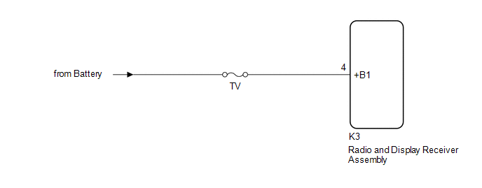
WIRING DIAGRAM
CAUTION / NOTICE / HINT
NOTICE:
- Depending on the parts that are replaced during vehicle inspection or maintenance, performing initialization, registration or calibration may be needed. Refer to Precaution for Navigation System.
Click here
.gif)
- When replacing the radio and display receiver assembly, always replace it with a new one. If a radio and display receiver assembly which was installed to another vehicle is used, the following may occur:
- A communication malfunction DTC may be stored.
- The radio and display receiver assembly may not operate normally.
- Inspect the fuses for circuits related to this system before performing the following procedure.
PROCEDURE
|
1. | CHECK VEHICLE SIGNAL (OPERATION CHECK) |
| (a) Enter the "Vehicle Signal Check Mode" screen. Refer to Check Vehicle Signal in Operation Check. Click here |
|
.png)
(b) Measure the battery voltage.
Standard Voltage:
11 to 14 V
HINT:
This display is updated once per second.
| NG | .gif) | GO TO STEP 3 |
|
.gif)
| 2. |
CHECK DTC |
(a) Clear the DTCs.
Body Electrical > Navigation System > Clear DTCs(b) Recheck for DTCs and check that no DTCs are output.
Body Electrical > Navigation System > Trouble CodesOK:
No DTCs are output.
| OK | |
END |
| NG | | REPLACE RADIO AND DISPLAY RECEIVER ASSEMBLY
|
| 3. |
CHECK HARNESS AND CONNECTOR (RADIO AND DISPLAY RECEIVER ASSEMBLY POWER SOURCE) |
(a) Disconnect the K3 radio and display receiver assembly connector.
(b) Measure the voltage according to the value(s) in the table below.
Standard Voltage:
|
Tester Connection | Condition |
Specified Condition |
|---|---|---|
|
K3-4 (+B1) - Body ground |
Always | 11 to 14 V |
| OK | | REPLACE RADIO AND DISPLAY RECEIVER ASSEMBLY
|
| NG | | REPAIR OR REPLACE HARNESS OR CONNECTOR |
READ NEXT:
 Stereo Component Amplifier Malfunction (B15A3)
DESCRIPTION This DTC is stored when a malfunction occurs in the stereo component amplifier assembly.
DTC No. Detection Item
DTC Detection Condition Trouble Area
B15A3 Stereo C
Navigation Processor Malfunction (B15AD)
DESCRIPTION These DTCs are stored when a malfunction occurs in the navigation ECU.
DTC No. Detection Item
DTC Detection Condition Trouble Area
B15AD Navigation Processor Malfu
GPS Antenna Connection Malfunction(short) (B15C0,B15C1)
DESCRIPTION These DTCs are stored when a malfunction occurs in the navigation antenna assembly.
DTC No. Detection Item
DTC Detection Condition Trouble Area
B15C0 GPS Antenna C
SEE MORE:
Abbreviations Used In Manual
ABBREVIATIONS USED IN MANUAL
Abbreviation Meaning
ABS Anti-Lock Brake System
A/C Air Conditioner
AC Alternating Current
ACC Accessory
ACIS Acoustic Control Induction System
ACM Active Control Engine Mount
ACSD Automatic Co
Child restraint system fixed with a child restraint LATCH anchor
■ Child restraint LATCH anchors
LATCH anchors are provided
for the outboard rear seats.
(Marks displaying the location
of the anchors are attached to
the seats.)
■ When installing in the rear outboard seats
Install the child restraint system in accordance to the operation
manual encl
