Toyota Camry (XV70): Brake Hold Switch
Components
COMPONENTS
ILLUSTRATION
|
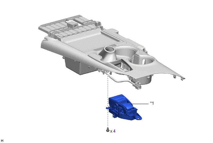
*1 | BRAKE HOLD SWITCH (ELECTRIC PARKING BRAKE SWITCH ASSEMBLY) |
- | - |
Removal
REMOVAL
PROCEDURE
1. PRECAUTION
Click here .gif)
2. REMOVE REAR UPPER CONSOLE PANEL SUB-ASSEMBLY
Click here
3. REMOVE BRAKE HOLD SWITCH (ELECTRIC PARKING BRAKE SWITCH ASSEMBLY)
| (a) Disengage the clamp and guide. |
|
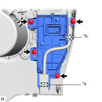
(b) Remove the 4 screws and brake hold switch (electric parking brake switch assembly).
Inspection
INSPECTION
PROCEDURE
1. INSPECT BRAKE HOLD SWITCH (ELECTRIC PARKING BRAKE SWITCH ASSEMBLY)
| (a) Make sure that there is no looseness in the locking part and the connecting part of the connector. OK: The connector is securely connected. |
|
(b) Disconnect the brake hold switch (electric parking brake switch assembly) connector.
(c) Check both the connector case and the terminal for deformation and corrosion.
OK:
No deformation or corrosion.
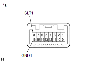
(d) Measure the resistance according to the value(s) in the table below.
Standard Resistance:
|
Tester Connection | Condition |
Specified Condition |
|---|---|---|
|
8 (SLT1) - 16 (GND1) |
Switch pushed | Below 1 Ω |
|
8 (SLT1) - 16 (GND1) |
Switch not pushed | 10 kΩ or higher |
If the result is not as specified, replace the brake hold switch (electric parking brake switch assembly).
Installation
INSTALLATION
PROCEDURE
1. INSTALL BRAKE HOLD SWITCH (ELECTRIC PARKING BRAKE SWITCH ASSEMBLY)
(a) Install the brake hold switch (electric parking brake switch assembly) with the 4 screws.
(b) Engage the guide and clamp.
2. INSTALL REAR UPPER CONSOLE PANEL SUB-ASSEMBLY
Click here .gif)
READ NEXT:
 Components
COMPONENTS ILLUSTRATION
*1 FRONT FENDER LINER
*2 FRONT SPEED SENSOR
*3 FRONT WHEEL OPENING EXTENSION PAD
*4 FRONT FLEXIBLE HOSE
Tightening torque f
Removal
REMOVAL CAUTION / NOTICE / HINT
HINT:
Use the same procedure for the RH side and LH side.
The following procedure is for the LH side.
The front speed sensor rotor is a component of the f
SEE MORE:
Components
COMPONENTS ILLUSTRATION
*1 REAR ARMREST ASSEMBLY
*2 REAR DOOR ARMREST COVER SUB-ASSEMBLY
*3 REAR DOOR INNER GLASS WEATHERSTRIP
*4 REAR DOOR NO. 2 SERVICE HOLE COVER
*5 REAR DOOR TRIM BOARD SUB-ASSEMBLY
*6 REAR POWER WINDOW REGULATOR SWITCH ASSE
No Sound can be Heard from Speakers
PROCEDURE
1. CHECK AUDIO SETTINGS
(a) In sound output setting mode, set volume, fader and balance to the initial values and check that the sound is normal.
OK: Audio system returns to normal. HINT: Sound quality adjustment measures vary according to the type of amplifier.
OK
