Toyota Camry (XV70): Brake Switch "A" Circuit Short to Battery (P057112)
DESCRIPTION
The skid control ECU (brake actuator assembly) receives stop light switch assembly signals and uses them to determine whether or not the brakes are applied.
DTCs may be stored if either of the following occurs:
- Stop light switch assembly stuck on malfunction.
- The accelerator and brake pedals are depressed simultaneously.*
HINT:
*: The skid control ECU (brake actuator assembly) may store this DTC upon judging that a stuck on malfunction has occurred when the accelerator pedal and brake pedal are depressed simultaneously. However, this does not indicate a malfunction.
|
DTC No. | Detection Item |
DTC Detection Condition | Trouble Area |
|---|---|---|---|
|
P057112 | Brake Switch "A" Circuit Short to Battery |
The vehicle speed is 10 km/h (6 mph) or more, the accelerator pedal is depressed, the master cylinder pressure is 0.5 MPa (5.1 kgf/cm2, 72.5 psi) or less, and the stop light switch assembly is on for 60 seconds or more. |
|
- *: w/ Smart Key System.
WIRING DIAGRAM
Refer to DTC P057111.
Click here
.gif)
CAUTION / NOTICE / HINT
NOTICE:
- Inspect the fuses for circuits related to this system before performing the following procedure.
- After replacing the skid control ECU (brake actuator assembly), perform acceleration sensor zero point calibration and system information memorization.
Click here
- DTC precaution
Click here
Procedure to clear warning lights (When not clearing DTCs) Procedure
- Repair or replacement.
- Turn the ignition switch to ON.
- Drive the vehicle and depress the brake pedal 2 or 3 times to clear the warning lights.
PROCEDURE
|
1. | CHECK BRAKE PEDAL OR STOP LIGHT SWITCH ASSEMBLY INSTALLATION |
(a) Check the brake pedal height and stop light switch assembly installation.
Click here
OK:
The brake pedal height and stop light switch assembly installation are normal.
| NG | .gif) | ADJUST BRAKE PEDAL OR STOP LIGHT SWITCH ASSEMBLY
|
|
.gif)
| 2. |
CHECK HARNESS AND CONNECTOR (STOP LIGHT SWITCH ASSEMBLY OUTPUT CIRCUIT) |
| (a) Make sure that there is no looseness at the locking part and the connecting part of the connector. OK: The connector is securely connected. |
|
(b) Disconnect the A34 skid control ECU (brake actuator assembly) connector.
(c) Check both the connector case and the terminals for deformation and corrosion.
OK:
No deformation or corrosion.
(d) Measure the voltage according to the value(s) in the table below.
Standard Voltage:
|
Tester Connection | Condition |
Specified Condition |
|---|---|---|
|
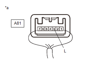
A81-3 (L) - Body ground |
Brake pedal released |
Below 1.5 V |
| OK | | REPLACE BRAKE ACTUATOR ASSEMBLY |
|
| 3. |
CHECK HARNESS AND CONNECTOR (STOP LIGHT SWITCH ASSEMBLY - BRAKE ACTUATOR ASSEMBLY) |
| (a) Make sure that there is no looseness at the locking part and the connecting part of the connector. OK: The connector is securely connected. |
|
(b) Disconnect the A34 skid control ECU (brake actuator assembly) connector.
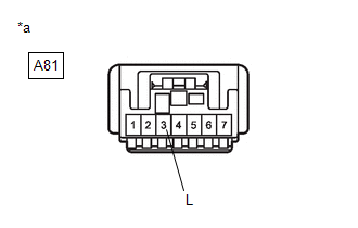
(c) Disconnect the A81 stop light switch assembly connector.
(d) Check both the connector case and the terminals for deformation and corrosion.
OK:
No deformation or corrosion.
(e) Measure the voltage according to the value(s) in the table below.
Standard Voltage:
|
Tester Connection | Condition |
Specified Condition |
|---|---|---|
|
A81-3 (L) - Body ground |
Always | Below 1.5 V |
| OK | | REPLACE STOP LIGHT SWITCH ASSEMBLY |
|
| 4. |
CHECK HARNESS AND CONNECTOR (STOP LIGHT SWITCH ASSEMBLY - ECM) |
| (a) Make sure that there is no looseness at the locking part and the connecting part of the connector. OK: The connector is securely connected. |
|
(b) Disconnect the A34 skid control ECU (brake actuator assembly) connector.
(c) Disconnect the A81 stop light switch assembly connector.
(d) Disconnect the A24 ECM connector (for A25A-FKS).
(e) Disconnect the A21 ECM connector (for 2GR-FKS).
(f) Check both the connector case and the terminals for deformation and corrosion.
OK:
No deformation or corrosion.
(g) Measure the voltage according to the value(s) in the table below.
Standard Voltage:
|
Tester Connection | Condition |
Specified Condition |
|---|---|---|
|
A81-3 (L) - Body ground |
Always | Below 1.5 V |
| OK | | REPLACE ECM for A25A-FKS: Click here for 2GR-FKS: Click here
|
|
| 5. |
CHECK HARNESS AND CONNECTOR (STOP LIGHT SWITCH ASSEMBLY - SHIFT LOCK CONTROL UNIT ASSEMBLY) |
| (a) Make sure that there is no looseness at the locking part and the connecting part of the connector. OK: The connector is securely connected. |
|
(b) Disconnect the A34 skid control ECU (brake actuator assembly) connector.
(c) Disconnect the A81 stop light switch assembly connector.
(d) Disconnect the A24 ECM connector (for A25A-FKS).
(e) Disconnect the A21 ECM connector (for 2GR-FKS).
(f) Disconnect the K27 shift lock control ECU (shift lock control unit assembly) connector (w/ Smart Key System).
(g) Disconnect the K28 shift lock control ECU (shift lock control unit assembly) connector (w/o Smart Key System).
(h) Check both the connector case and the terminals for deformation and corrosion.
OK:
No deformation or corrosion.
(i) Measure the voltage according to the value(s) in the table below.
Standard Voltage:
|
Tester Connection | Condition |
Specified Condition |
|---|---|---|
|
A81-3 (L) - Body ground |
Always | Below 1.5 V |
|
Result | Proceed to |
|---|---|
|
OK | A |
|
NG (w/ Smart Key System) | B |
|
NG (w/o Smart Key System) |
C |
| A |
| REPLACE SHIFT LOCK CONTROL UNIT ASSEMBLY for UB80E: Click here for UB80F: Click here
|
| C |
| REPAIR OR REPLACE HARNESS OR CONNECTOR |
|
| 6. |
CHECK HARNESS AND CONNECTOR (STOP LIGHT SWITCH ASSEMBLY - SMART KEY ECU ASSEMBLY) |
| (a) Make sure that there is no looseness at the locking part and the connecting part of the connector. OK: The connector is securely connected. |
|
(b) Disconnect the A34 skid control ECU (brake actuator assembly) connector.
(c) Disconnect the A81 stop light switch assembly connector.
(d) Disconnect the A24 ECM connector (for A25A-FKS).
(e) Disconnect the A21 ECM connector (for 2GR-FKS).
(f) Disconnect the K27 shift lock control ECU (shift lock control unit assembly) connector.
(g) Disconnect the R8 certification ECU (smart key ECU assembly) connector.
(h) Check both the connector case and the terminals for deformation and corrosion.
OK:
No deformation or corrosion.
(i) Measure the voltage according to the value(s) in the table below.
Standard Voltage:
|
Tester Connection | Condition |
Specified Condition |
|---|---|---|
|
A81-3 (L) - Body ground |
Always | Below 1.5 V |
| OK | | REPLACE SMART KEY ECU ASSEMBLY |
| NG | | REPAIR OR REPLACE HARNESS OR CONNECTOR |
READ NEXT:
 Brake Switch "A" Circuit Open (P057113)
DESCRIPTION The skid control ECU (brake actuator assembly) receives stop light switch assembly signals and uses them to determine whether or not the brakes are applied.
The skid control ECU (brake a
Control Module Communication Bus "B" Off Bus Off (U007488,...,U015187)
DESCRIPTION The skid control ECU (brake actuator assembly) communicates with the following ECUs and sensors via CAN communication.
ECM
TCM (ECM)
Yaw rate and acceleration sensor (airbag s
ABS Warning Light Remains ON
DESCRIPTION This procedure is for troubleshooting when the ABS warning light remains on but no DTCs are output.
The skid control ECU (brake actuator assembly) controls the ABS warning light in the c
SEE MORE:
Starter Relay Circuit Short to Battery (P061512)
MONITOR DESCRIPTION While the engine is being cranked, positive battery voltage is applied to terminal STA of the ECM. If the ECM detects the starter control (STA) signal while the vehicle is being driven, it determines that there is a malfunction in the STA circuit. The ECM then illuminates the MIL
Transmission Range Sensor "A" Circuit Open (P070513,P070562)
DESCRIPTION The park/neutral position switch assembly detects the shift lever position and sends signals to the ECM.
DTC No. Detection Item
DTC Detection Condition Trouble Area
MIL Memory
Note P070513
Transmission Range Sensor "A" Circuit Open
When the engi
