Toyota Camry (XV70): Check Mode Procedure
CHECK MODE PROCEDURE
DESCRIPTION
(a) Check mode has a higher sensitivity to malfunctions and can detect malfunctions that normal mode cannot detect. Check mode can also detect all of the malfunctions that normal mode can detect. In check mode, DTCs are detected with 1 trip detection logic.
CHECK MODE PROCEDURE
(a) Make sure that the following conditions are met:
- The battery voltage is 11 V or more.
- The throttle valve is fully closed.
- The shift lever is in P or N.
- The air conditioning is off.
(b) Connect the Techstream to the DLC3.
(c) Turn the engine switch on (IG).
(d) Turn the Techstream on.
(e) Enter the following menus: Powertrain / Transmission / Utility / Check Mode.
Powertrain > Transmission > Utility|
Tester Display |
|---|
| Check Mode |
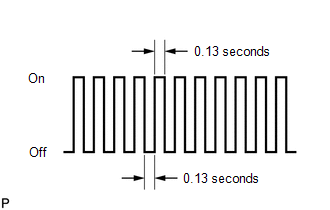
(f) Change the ECM to check mode and check that the MIL flashes as shown in the illustration.
NOTICE:
All DTCs and freeze frame data will be cleared if: 1) the Techstream is used to change the ECM from normal mode to check mode or vice versa; or 2) during check mode, the engine switch is turned from on (IG) to off.
Before entering check mode, make a note of the DTCs and freeze frame data.
(g) Start the engine. The MIL should turn off after the engine starts.
(h) Perform Monitor Drive Pattern for the ECT.
Click here
.gif)
(Or, simulate the conditions of the malfunction described by the customer.)
(i) After simulating the malfunction conditions, use the Techstream to check for DTCs and freeze frame data.
READ NEXT:
 Fail-safe Chart
FAIL-SAFE CHART Description The fail-safe function minimizes the loss of operation when a malfunction occurs in a sensor or solenoid.
Fail-safe (a) Fail-safe control list:
Malfunctioning Part
Data List / Active Test
DATA LIST / ACTIVE TEST DATA LIST NOTICE:
In the table below, the values listed under "Normal Condition" are reference values. Do not depend solely on these reference values when deciding whether a
Diagnostic Trouble Code Chart
DIAGNOSTIC TROUBLE CODE CHART Automatic Transaxle System
DTC No. Detection Item
MIL Memory
Note Link
P050031 Vehicle Speed Sensor "A" No Signal
Comes on DTC sto
SEE MORE:
Inspection
INSPECTION PROCEDURE 1. INSPECT STEERING HEATER SWITCH
(a) Remove the steering heater switch. Click here
*a Component without harness connected
(Steering Heater Switch)
(b) Measure the resistance according to the value(s) in the table
Disassembly
DISASSEMBLY PROCEDURE 1. REMOVE GENERATOR PULLEY CAP
(a) Using a screwdriver, remove the generator pulley cap from the generator pulley with clutch.
NOTICE:
Do not reuse the generator pulley cap.
If the generator pulley cap is removed, replace the generator pulley cap and generat
