Toyota Camry (XV70): Fail-safe Chart
FAIL-SAFE CHART
Description
The fail-safe function minimizes the loss of operation when a malfunction occurs in a sensor or solenoid.
Fail-safe
(a) Fail-safe control list:
|
Malfunctioning Part | Function |
|---|---|
|
Transmission Revolution Sensor (NT) |
|
| Transmission Revolution Sensor (NC) |
|
| Solenoid (SL1, SL2, SL3, SL4, SL5, SL6, SLT, SLU and SL) valve |
If the ECM detects a solenoid valve malfunction, it performs fail-safe control. |
|
ATF temperature sensor |
|
| ECM power supply (voltage is low) |
|
| Knock sensor |
|
| CAN communication |
|
| Solenoid (SLU) valve |
|
| Solenoid (SLT) valve |
|
(b) Solenoid Valve Normal Operation Chart:
|
Gear | 1st |
2nd | 3rd |
4th | 5th |
6th | 7th |
8th |
|---|---|---|---|---|---|---|---|---|
| Solenoid (SL1) Valve |
ON | ON |
ON | ON |
ON | OFF |
OFF | OFF |
|
Solenoid (SL2) Valve |
OFF | OFF |
OFF | OFF |
ON | ON |
ON | ON |
|
Solenoid (SL3) Valve |
OFF | OFF |
ON | OFF |
OFF | OFF |
ON | OFF |
|
Solenoid (SL4) Valve |
OFF | OFF |
OFF | ON |
OFF | ON |
OFF | OFF |
|
Solenoid (SL5) Valve |
OFF | ON |
OFF | OFF |
OFF | OFF |
OFF | ON |
|
Solenoid (SL6) Valve | ON |
OFF | OFF |
OFF | OFF |
OFF | OFF |
OFF |
(c) Fail-safe Control Chart:
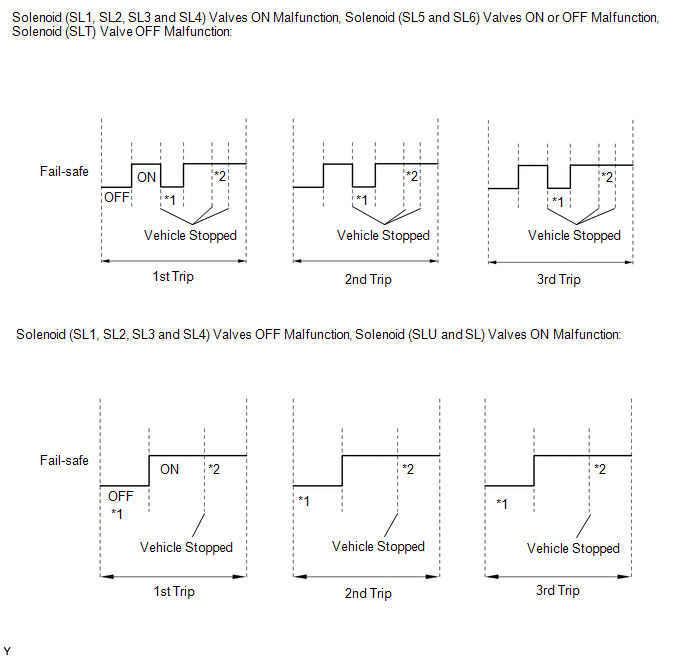
*1: Operation of fail-safe is canceled the first time the vehicle is stopped.
*2: Operation of fail-safe is not canceled for subsequent times the vehicle is stopped.
Fail-safe operation is performed when the ECM detects a malfunction.
Fail-safe Control Chart (Solenoid (SL1) Valve)|
Gear Under Normal Conditions |
1st | 2nd |
3rd | 4th |
5th | 6th |
7th | 8th |
|---|---|---|---|---|---|---|---|---|
| *: Neutral | ||||||||
| ON malfunction (without fail-safe control) |
1st | 2nd |
3rd | 4th |
5th | 4th to 5th |
3rd to 5th | 5th |
|
Fail-safe control during ON malfunction |
1st | 2nd |
3rd | 4th |
5th | 5th |
5th | 5th |
|
OFF malfunction (without fail-safe control) |
N* | N* |
N* | N* |
N* | 6th |
7th | 8th |
|
Fail-safe control during OFF malfunction |
6th | 6th |
6th | 6th |
6th | 6th |
7th | 8th |
|
Gear Under Normal Conditions |
1st | 2nd |
3rd | 4th |
5th | 6th |
7th | 8th |
|---|---|---|---|---|---|---|---|---|
| *: Neutral | ||||||||
| ON malfunction (without fail-safe control) |
5th | 5th |
3rd to 5th | 4th to 5th |
5th | 6th |
7th | 8th |
|
Fail-safe control during ON malfunction |
5th | 5th |
5th | 5th |
5th | 6th |
7th | 8th |
|
OFF malfunction (without fail-safe control) |
1st | 2nd |
3rd | 4th |
N* | N* |
N* | N* |
|
Fail-safe control during OFF malfunction |
1st | 2nd |
3rd | 4th |
4th | 4th |
4th | 4th |
|
Gear Under Normal Conditions |
1st | 2nd |
3rd | 4th |
5th | 6th |
7th | 8th |
|---|---|---|---|---|---|---|---|---|
| *: Neutral | ||||||||
| ON malfunction (without fail-safe control) |
3rd | 3rd |
3rd | 3rd |
3rd to 5th | 7th |
7th | 7th |
|
Fail-safe control during ON malfunction |
3rd | 3rd |
3rd | 3rd |
3rd | 7th |
7th | 7th |
|
OFF malfunction (without fail-safe control) |
1st | 2nd |
N* | 4th |
5th | 6th |
N* | 8th |
|
Fail-safe control during OFF malfunction |
1st | 2nd |
4th | 4th |
5th | 6th |
6th | 8th |
|
Gear Under Normal Conditions |
1st | 2nd |
3rd | 4th |
5th | 6th |
7th | 8th |
|---|---|---|---|---|---|---|---|---|
| *: Neutral | ||||||||
| ON malfunction (without fail-safe control) |
4th | 4th |
3rd | 4th |
4th to 5th | 6th |
7th | 6th |
|
Fail-safe control during ON malfunction |
4th | 4th |
4th | 4th |
4th | 6th |
6th | 6th |
|
OFF malfunction (without fail-safe control) |
1st | 2nd |
3rd | N* |
5th | N* |
7th | 8th |
|
Fail-safe control during OFF malfunction |
1st | 2nd |
3rd | 5th |
5th | 7th |
7th | 8th |
|
Gear Under Normal Conditions |
1st | 2nd |
3rd | 4th |
5th | 6th |
7th | 8th |
|---|---|---|---|---|---|---|---|---|
| *: Neutral | ||||||||
| ON malfunction (without fail-safe control) |
N* | 2nd |
3rd | 4th |
5th | 6th |
7th | 8th |
|
Fail-safe control during ON malfunction |
2nd | 2nd |
3rd | 4th |
5th | 6th |
7th | 8th |
|
OFF malfunction (without fail-safe control) |
1st | N* |
3rd | 4th |
5th | 6th |
7th | N* |
|
Fail-safe control during OFF malfunction |
3rd | 3rd |
3rd | 4th |
5th | 6th |
7th | 7th |
|
Gear Under Normal Conditions |
1st | 2nd |
3rd | 4th |
5th | 6th |
7th | 8th |
|---|---|---|---|---|---|---|---|---|
| *: Neutral | ||||||||
| ON malfunction (without fail-safe control) |
1st | N* |
3rd | 4th |
5th | 6th |
7th | N* |
|
Fail-safe control during ON malfunction |
3rd | 3rd |
3rd | 4th |
5th | 6th |
7th | 7th |
|
OFF malfunction (without fail-safe control) |
N* | 2nd |
3rd | 4th |
5th | 6th |
7th | 8th |
|
Fail-safe control during OFF malfunction |
2nd | 2nd |
3rd | 4th |
5th | 6th |
7th | 8th |
|
Gear Under Normal Conditions |
1st | 2nd |
3rd | 4th |
5th | 6th |
7th | 8th |
|---|---|---|---|---|---|---|---|---|
|
OFF malfunction (without fail-safe control) (MAX Pressure) |
1st | 5th |
3rd to 5th | 4th to 5th |
5th | 4th to 5th |
3rd to 5th | 5th |
|
Fail-safe control during ON malfunction |
Fixed in 5th | |||||||
|
Gear Under Normal Conditions |
1st | 2nd |
3rd | 4th |
5th | 6th |
7th | 8th |
|---|---|---|---|---|---|---|---|---|
| *: Neutral | ||||||||
| ON malfunction (without fail-safe control) |
1st | 2nd |
3rd or N* | 4th or N* |
5th | 6th or N* |
7th or N* | 8th |
|
Fail-safe control during ON malfunction |
1st | 2nd |
5th | 5th |
5th | 5th |
5th | 8th |
|
Gear Under Normal Conditions |
1st | 2nd |
3rd | 4th |
5th | 6th |
7th | 8th |
|---|---|---|---|---|---|---|---|---|
| *: Neutral | ||||||||
| ON malfunction (without fail-safe control) (MIN Pressure) | 1st |
2nd | 3rd or N* |
4th or N* | 5th |
6th or N* | 7th or N* |
8th |
| Fail-safe control during ON malfunction |
1st | 2nd |
5th | 5th |
5th | 5th |
5th | 8th |
HINT:
In the case of an open or short, the ECM stops sending current to the open or shorted solenoid.
READ NEXT:
 Data List / Active Test
DATA LIST / ACTIVE TEST DATA LIST NOTICE:
In the table below, the values listed under "Normal Condition" are reference values. Do not depend solely on these reference values when deciding whether a
Diagnostic Trouble Code Chart
DIAGNOSTIC TROUBLE CODE CHART Automatic Transaxle System
DTC No. Detection Item
MIL Memory
Note Link
P050031 Vehicle Speed Sensor "A" No Signal
Comes on DTC sto
Vehicle Control History
VEHICLE CONTROL HISTORY VEHICLE CONTROL HISTORY
HINT: A part of the control history can be confirmed using the vehicle control history.
Click here
SEE MORE:
Tire information
Typical tire symbols
Full-size tire
Compact spare tire
Tire size
Summer tires or all season tires
An all season tire has "M+S" on the sidewall. A tire not marked "M+S"
is a summer tire.
TUBELESS or TUBE TYPE
A tubeless tire does not have a tube and air is directly put into the
Components
COMPONENTS ILLUSTRATION
*1 CAMSHAFT TIMING GEAR BOLT
*2 O-RING
*3 CAMSHAFT TIMING OIL CONTROL SOLENOID ASSEMBLY (for Intake Side of Bank 2)
- -
N*m (kgf*cm, ft.*lbf): Specified torque
● Non-reusable part
Adhesive 1324
