Toyota Camry (XV70): Components
COMPONENTS
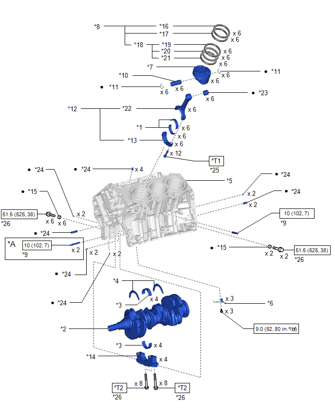
ILLUSTRATION
|
*A | w/ Stud Bolt |
- | - |
|
*1 | CONNECTING ROD BEARING |
*2 | CRANKSHAFT |
|
*3 | CRANKSHAFT BEARING |
*4 | CRANKSHAFT THRUST WASHER SET |
|
*5 | CYLINDER BLOCK SUB-ASSEMBLY |
*6 | NO. 1 OIL NOZZLE SUB-ASSEMBLY |
|
*7 | PISTON |
*8 | PISTON RING SET |
|
*9 | STUD BOLT |
*10 | PISTON PIN |
|
*11 | PISTON PIN HOLE SNAP RING |
*12 | CONNECTING ROD SUB-ASSEMBLY |
|
*13 | CONNECTING ROD CAP |
*14 | CRANKSHAFT BEARING CAP |
|
*15 | SEAL WASHER |
*16 | NO. 1 COMPRESSION RING |
|
*17 | NO. 2 COMPRESSION RING |
*18 | OIL RING |
|
*19 | UPPER SIDE RAIL |
*20 | OIL RING EXPANDER |
|
*21 | LOWER SIDE RAIL |
*22 | CONNECTING ROD |
|
*23 | CONNECTING ROD SMALL END BUSH |
*24 | STRAIGHT PIN |
|
*25 | CONNECTING ROD BOLT |
*26 | CRANKSHAFT BEARING CAP SET BOLT |
.png) |
N*m (kgf*cm, ft.*lbf): Specified torque |
● | Non-reusable part |
|
*T1 | 1st: 24.5 (250, 18) 2nd: Turn 90° | *T2 |
1st: 61 (622, 45) 2nd: Turn 90° |
READ NEXT:
 Disassembly
DISASSEMBLY CAUTION / NOTICE / HINT
The necessary procedures (adjustment, calibration, initialization, or registration) that must be performed after parts are removed and installed, or replaced duri
Inspection
INSPECTION PROCEDURE 1. INSPECT CONNECTING ROD THRUST CLEARANCE
(a) Install the connecting rod cap. Click here
(b) Using a dial indicator, measure the thrust clearance while moving the co
Replacement
REPLACEMENT PROCEDURE 1. REPLACE STRAIGHT PIN
NOTICE: If a straight pin is deformed, replace it. (a) Using a plastic hammer, tap in new straight pins to the cylinder block sub-assembly.
*
SEE MORE:
Installation
INSTALLATION PROCEDURE 1. TEMPORARILY INSTALL FUEL (ENGINE ROOM SIDE) PUMP ASSEMBLY
(a) Turn the crankshaft pulley until the flat of the camshaft faces the fuel pump lifter assembly.
HINT: This prevents the camshaft nose from pushing up the fuel pump lifter assembly when installing the fuel
USB charging ports
The USB charging ports are used to supply 2.5 A (USB Type-A port)
or 3.0 A (USB Type-C port) of electricity at 5 V to external devices.
The USB charging ports are for charging only. They are not designed
for data transfer or other purposes.
Depending on the external device, it may not charge
© 2023-2025 Copyright www.tocamry.com
