Toyota Camry (XV70): Disassembly
DISASSEMBLY
CAUTION / NOTICE / HINT
HINT:
- Use the same procedure for the LH side and RH side.
- The following procedure is for the LH side.
PROCEDURE
1. REMOVE REAR WHEEL
Click here
.gif)
2. SEPARATE REAR DISC BRAKE CALIPER ASSEMBLY
Click here
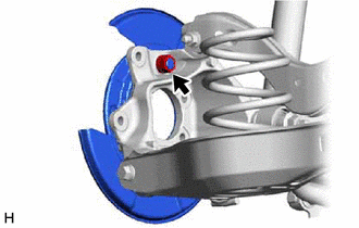
3. REMOVE PARKING BRAKE SHOE ADJUSTING HOLE PLUG
Click here
4. REMOVE REAR DISC
Click here
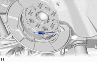
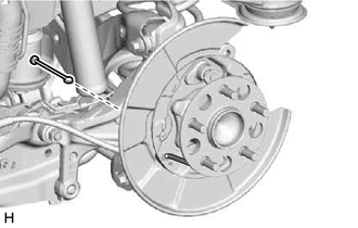
5. REMOVE PARKING BRAKE SHOE RETURN TENSION SPRING (for Front Side)
| (a) Remove the parking brake shoe return tension spring. |
|
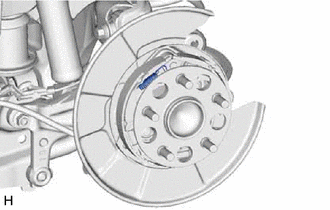
6. REMOVE PARKING BRAKE SHOE RETURN TENSION SPRING (for Rear Side)
| (a) Remove the parking brake shoe return tension spring. |
|
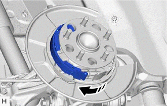
7. REMOVE PARKING BRAKE SHOE STRUT
| (a) Pull the No. 1 parking brake shoe assembly towards the front of the vehicle by hand as shown in the illustration. |
|
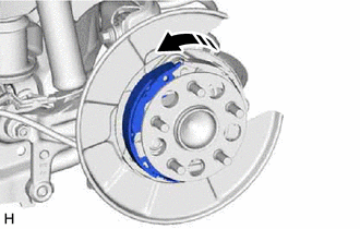
| (b) Remove the parking brake shoe strut. |
|
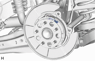
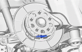
8. REMOVE PARKING BRAKE SHOE RETURN TENSION SPRING (for Lower Side)
| (a) Remove the parking brake shoe return tension spring. |
|
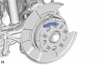
9. REMOVE PARKING BRAKE SHOE ADJUSTING SCREW SET
| (a) Pull the No. 1 parking brake shoe assembly towards the front of the vehicle by hand as shown in the illustration. |
|
| (b) Remove the parking brake shoe adjusting screw set. |
|
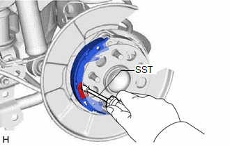
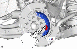
10. REMOVE NO. 1 PARKING BRAKE SHOE ASSEMBLY (for Front Side)
| (a) Using SST, remove the parking brake shoe hold down spring and No. 1 parking brake shoe assembly. SST: 09718-00011 |
|
11. REMOVE PARKING BRAKE SHOE HOLD DOWN SPRING PIN (for Front Side)
| (a) Remove the parking brake shoe hold down spring pin. |
|
12. REMOVE NO. 1 PARKING BRAKE SHOE ASSEMBLY (for Rear Side)
| (a) Using SST, remove the parking brake shoe hold down spring and No. 1 parking brake shoe assembly. SST: 09718-00011 |
|
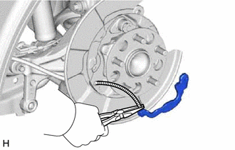
13. REMOVE PARKING BRAKE SHOE LEVER
| (a) Using needle-nose pliers, remove the parking brake shoe lever from the No. 3 parking brake cable assembly. |
|
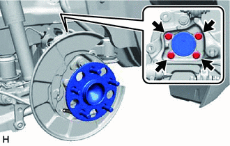
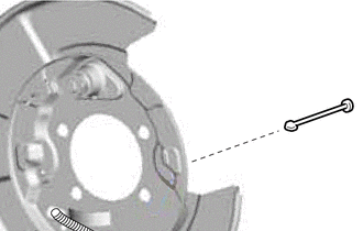
14. REMOVE PARKING BRAKE SHOE HOLD DOWN SPRING PIN (for Rear Side)
(a) Disconnect the skid control sensor wire.
Click here
| (b) Remove the 4 bolts and rear axle hub and bearing assembly from the rear axle carrier sub-assembly. |
|
| (c) Remove the nut and separate the backing plate from the rear axle carrier sub-assembly. NOTICE: Use wire or an equivalent tool to keep the backing plate from hanging by the No. 3 parking brake cable assembly. |
|
| (d) Remove the parking brake shoe hold down spring pin from the backing plate. |
|
READ NEXT:
 Inspection
INSPECTION PROCEDURE 1. INSPECT BRAKE DISC INSIDE DIAMETER
(a) Using a brake drum gauge or an equivalent tool, measure the inside diameter of the rear disc.
Standard Inside Diameter: 173 mm
Reassembly
REASSEMBLY CAUTION / NOTICE / HINT
HINT:
Use the same procedure for the LH side and RH side.
The following procedure is for the LH side.
PROCEDURE 1. INSTALL PARKING BRAKE SHOE HOLD DOWN
SEE MORE:
Driving assist systems
To keep driving safety and performance, the following systems
operate automatically in response to various driving situations.
Be aware, however, that these systems are supplementary and
should not be relied upon too heavily when operating the vehicle.
◆ ABS (Anti-lock Brake System)
Helps t
FR Speed Sensor Wrong Installation (X0452)
DESCRIPTION
Code Tester Display
Measurement Item Trouble Area
X0452 FR Speed Sensor Wrong Installation
History of front speed sensor RH being installed incorrectly
Front Speed Sensor RH PROCEDURE
1.
CHECK FOR DTCs (HEALTH CHECK) (a) Perform the H
