Toyota Camry (XV70): ECM Power Source Circuit
DESCRIPTION
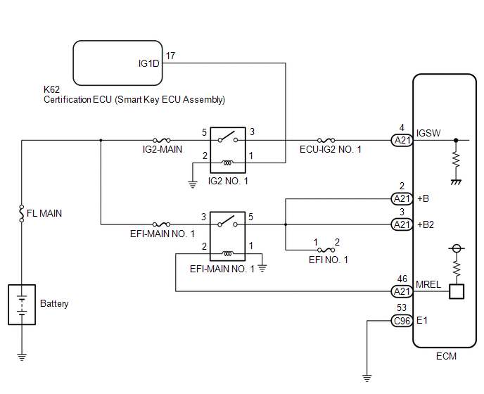
When the engine switch is turned on (IG), the battery voltage is applied to the IGSW terminal of the ECM.
The output signal from the MREL terminal of the ECM causes a current to flow to the coil of the EFI-MAIN NO. 1 relay, closing the contacts and supplying power to terminals +B and +B2 of the ECM.
WIRING DIAGRAM
CAUTION / NOTICE / HINT
NOTICE:
Inspect the fuses for circuits related to this system before performing the following inspection procedure.
PROCEDURE
| 1. |
CHECK HARNESS AND CONNECTOR (ECM - BODY GROUND) |
(a) Disconnect the ECM connector.
(b) Measure the resistance according to the value(s) in the table below.
Standard Resistance:
|
Tester Connection | Condition |
Specified Condition |
|---|---|---|
|
C96-53 (E1) - Body ground |
Always | Below 1 Ω |
| NG | .gif) | REPAIR OR REPLACE HARNESS OR CONNECTOR |
|
.gif)
| 2. |
CHECK TERMINAL VOLTAGE (IGSW TERMINAL VOLTAGE) |
| (a) Disconnect the ECM connector. |
|
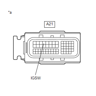
(b) Measure the voltage according to the value(s) in the table below.
Standard Voltage:
|
Tester Connection | Condition |
Specified Condition |
|---|---|---|
|
A21-4 (IGSW) - Body ground |
Engine switch on (IG) |
11 to 14 V |
| NG | | GO TO STEP 7 |
|
| 3. |
INSPECT EFI-MAIN NO. 1 RELAY |
(a) Inspect the EFI-MAIN NO. 1 relay.
Click here .gif)
| NG | | REPLACE EFI-MAIN NO. 1 RELAY |
|
| 4. |
CHECK HARNESS AND CONNECTOR (EFI-MAIN NO. 1 RELAY - ECM) |
(a) Disconnect the ECM connector.
(b) Remove the EFI-MAIN NO. 1 relay from the engine room relay block and junction block assembly.
HINT:
Remove the EFI-MAIN NO. 2 and EFI-MAIN NO. 3 relays connected between the checked terminals as the coil inside the relay influences the measurement value.
(c) Measure the resistance according to the value(s) in the table below.
Standard Resistance:
|
Tester Connection | Condition |
Specified Condition |
|---|---|---|
|
2 (EFI-MAIN NO.1 relay) - A21-46 (MREL) |
Always | Below 1 Ω |
|
5 (EFI-MAIN NO.1 relay) - A21-2 (+B) |
Always | Below 1 Ω |
|
5 (EFI-MAIN NO.1 relay) - A21-3 (+B2) |
Always | Below 1 Ω |
|
2 (EFI-MAIN NO.1 relay) or A21-46 (MREL) - Body ground and other terminals |
Always | 10 kΩ or higher |
|
5 (EFI-MAIN NO.1 relay) or A21-2 (+B) - Body ground and other terminals |
Always | 10 kΩ or higher |
|
5 (EFI-MAIN NO.1 relay) or A21-3 (+B2) - Body ground and other terminals |
Always | 10 kΩ or higher |
| NG | | REPAIR OR REPLACE HARNESS OR CONNECTOR |
|
| 5. |
CHECK TERMINAL VOLTAGE (POWER SOURCE OF EFI-MAIN NO. 1 RELAY) |
|
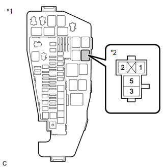
*1 | Engine Room Relay Block and Junction Block Assembly |
|
*2 | EFI-MAIN NO. 1 Relay |
(a) Remove the EFI-MAIN NO. 1 relay from the engine room relay block and junction block assembly.
(b) Measure the voltage according to the value(s) in the table below.
Standard Voltage:
|
Tester Connection | Condition |
Specified Condition |
|---|---|---|
|
3 (EFI-MAIN NO. 1 relay) - Body ground |
Always | 11 to 14 V |
| NG | | REPAIR OR REPLACE HARNESS OR CONNECTOR (BATTERY - EFI-MAIN NO. 1 RELAY) |
|
| 6. |
CHECK HARNESS AND CONNECTOR (EFI-MAIN NO. 1 RELAY - BODY GROUND) |
(a) Remove the EFI-MAIN NO. 1 relay from the engine room relay block and junction block assembly.
(b) Measure the resistance according to the value(s) in the table below.
Standard Resistance:
|
Tester Connection | Condition |
Specified Condition |
|---|---|---|
|
1 (EFI-MAIN NO. 1 relay) - Body ground |
Always | Below 1 Ω |
| OK | | PROCEED TO NEXT SUSPECTED AREA SHOWN IN PROBLEM SYMPTOMS TABLE
|
| NG | | REPAIR OR REPLACE HARNESS OR CONNECTOR |
| 7. |
INSPECT IG2 NO. 1 RELAY |
(a) Inspect the IG2 NO. 1 relay.
Click here
| NG | | REPLACE IG2 NO. 1 RELAY |
|
| 8. |
CHECK HARNESS AND CONNECTOR (IG2 NO. 1 RELAY - ECM) |
(a) Disconnect the ECM connector.
(b) Remove the IG2 NO. 1 relay from the engine room relay block and junction block assembly.
(c) Measure the resistance according to the value(s) in the table below.
Standard Resistance:
|
Tester Connection | Condition |
Specified Condition |
|---|---|---|
|
3 (IG2 NO. 1 relay) - A21-4 (IGSW) |
Always | Below 1 Ω |
|
3 (IG2 NO. 1 relay) or A21-4 (IGSW) - Body ground and other terminals |
Always | 10 kΩ or higher |
| NG | | REPAIR OR REPLACE HARNESS OR CONNECTOR |
|
| 9. |
CHECK TERMINAL VOLTAGE (POWER SOURCE OF IG2 NO. 1 RELAY) |
|
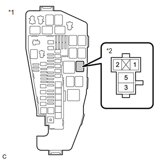
*1 | Engine Room Relay Block and Junction Block Assembly |
|
*2 | IG2 NO. 1 Relay |
(a) Remove the IG2 NO. 1 relay from the engine room relay block and junction block assembly.
(b) Measure the voltage according to the value(s) in the table below.
Standard Voltage:
|
Tester Connection | Condition |
Specified Condition |
|---|---|---|
|
5 (IG2 NO. 1 relay) - Body ground |
Always | 11 to 14 V |
| NG | | REPAIR OR REPLACE HARNESS OR CONNECTOR (BATTERY - IG2 NO. 1 RELAY) |
|
| 10. |
CHECK HARNESS AND CONNECTOR (IG2 NO. 1 RELAY - BODY GROUND) |
(a) Remove the IG2 NO. 1 relay from the engine room relay block and junction block assembly.
(b) Measure the resistance according to the value(s) in the table below.
Standard Resistance:
|
Tester Connection | Condition |
Specified Condition |
|---|---|---|
|
2 (IG2 NO. 1 relay) - Body ground |
Always | Below 1 Ω |
| NG | | REPAIR OR REPLACE HARNESS OR CONNECTOR |
|
| 11. |
CHECK HARNESS AND CONNECTOR (CERTIFICATION ECU (SMART KEY ECU ASSEMBLY) - IG2 NO. 1 RELAY) |
(a) Disconnect the certification ECU (smart key ECU assembly) connector.
(b) Remove the IG2 NO. 1 relay from the engine room relay block and junction block assembly.
(c) Measure the resistance according to the value(s) in the table below.
Standard Resistance:
|
Tester Connection | Condition |
Specified Condition |
|---|---|---|
|
K62-17 (IG1D) - 1 (IG2 NO. 1 relay) |
Always | Below 1 Ω |
|
K62-17 (IG1D) or 1 (IG2 NO. 1 relay) - Body ground and other terminals |
Always | 10 kΩ or higher |
| OK | | CHECK SMART KEY SYSTEM
|
| NG | | REPAIR OR REPLACE HARNESS OR CONNECTOR |
READ NEXT:
 VC Output Circuit
DESCRIPTION The ECM constantly generates a 5 V power source voltage from the battery voltage supplied to the +B, +B2 (BATT) terminals to operate the microprocessor. The ECM also provides this power to
Fuel Pump Control Circuit
DESCRIPTION The fuel pump (for low pressure side) circuit consists of the ECM, fuel pump (for low pressure side) and fuel pump control ECU (which operates the fuel pump (for low pressure side)). Based
Starter Signal Circuit
DESCRIPTION While the engine is being cranked, current flows from terminal STAR of the certification ECU (smart key ECU assembly) to the park/neutral position switch assembly and to terminal STA of th
SEE MORE:
Crankshaft Position - Camshaft Position Correlation Bank 1 Sensor B (P001700,P001900)
DESCRIPTION In the VVT (Variable Valve Timing) system, the appropriate exhaust valve open and close timing is controlled by the ECM. The ECM performs exhaust valve control by performing the following: 1) controlling the exhaust camshaft cam timing oil control solenoid assembly, camshaft timing gear
Reassembly
REASSEMBLY PROCEDURE 1. INSTALL FUEL PUMP
HINT: Perform "Inspection After Repair" after replacing the fuel pump.
Click here
(a) Apply gasoline to a new O-ring. Then install the O-ring and fuel pump spacer to the fuel pump.
*1 O-ring
*2 Fu
