Toyota Camry (XV70): Fuel Pump Control Circuit
DESCRIPTION
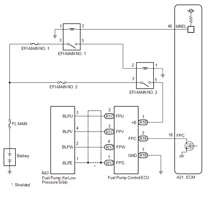
The fuel pump (for low pressure side) circuit consists of the ECM, fuel pump (for low pressure side) and fuel pump control ECU (which operates the fuel pump (for low pressure side)). Based on the engine output, the ECM determines the fuel pump speed. The speed is then converted to a duty signal and sent to the fuel pump control ECU. Based on the signal sent from the ECM, the fuel pump control ECU adjusts the fuel pump (for low pressure side) operation speed.
WIRING DIAGRAM
CAUTION / NOTICE / HINT
NOTICE:
Inspect the fuses for circuits related to this system before performing the following procedure.
PROCEDURE
| 1. |
CHECK FUEL LEAK |
(a) Check around and beneath the vehicle for fuel leaks, fumes, etc.
OK:
No fuel leaks present.
| NG | .gif) | REPAIR OR REPLACE FUEL LEAK POINT |
|
.gif)
| 2. |
PERFORM ACTIVE TEST USING TECHSTREAM (ACTIVATE THE CIRCUIT RELAY) |
(a) Connect the Techstream to the DLC3.
(b) Turn the engine switch on (IG).
(c) Turn the Techstream on.
(d) Enter the following menus: Powertrain / Engine / Active Test / Activate the Circuit Relay.
Powertrain > Engine > Active Test|
Tester Display |
|---|
| Activate the Circuit Relay |
Standard:
|
Techstream Operation | Standard |
|---|---|
|
ON | Operating sounds can be heard from fuel pump (for low pressure side) |
| NG | | GO TO STEP 8 |
|
| 3. |
PERFORM ACTIVE TEST USING TECHSTREAM (CONTROL THE FUEL PUMP DUTY RATIO) |
(a) Install the fuel pressure gauge (for low pressure line of low pressure side).
Click here .gif)
(b) Connect the Techstream to the DLC3.
(c) Turn the engine switch on (IG).
(d) Turn the Techstream on.
(e) Enter the following menus: Powertrain / Engine / Active Test / Control the Fuel Pump Duty Ratio / Data List / Fuel Pressure (Low) / Fuel Pressure 2.
Powertrain > Engine > Active Test|
Active Test Display |
|---|
|
Control the Fuel Pump Duty Ratio |
|
Data List Display |
|---|
|
Fuel Pressure (Low) / Fuel Pressure 2 |
Standard:
|
Techstream Operation | Standard |
|---|---|
|
Low | Data List value and fuel pressure gauge are within +/-50 kPag of each other |
|
High |
HINT:
Perform "Inspection After Repair" after replacing the fuel pressure sensor (for low pressure side).
Click here
| NG | | REPLACE FUEL DELIVERY PIPE WITH SENSOR ASSEMBLY (FUEL PRESSURE SENSOR (FOR LOW PRESSURE SIDE))
|
|
| 4. |
READ VALUE USING TECHSTREAM (FUEL PRESSURE) |
(a) Connect the Techstream to the DLC3.
(b) Turn the engine switch on (IG).
(c) Turn the Techstream on.
(d) Enter the following menus: Powertrain / Engine / Data List / Target Fuel Pressure (Low) / Target Fuel Pressure 2, Fuel Pressure (Low) / Fuel Pressure 2 and Low Fuel Pressure Sensor.
Powertrain > Engine > Data List|
Tester Display |
|---|
| Target Fuel Pressure (Low) / Target Fuel Pressure 2 |
|
Fuel Pressure (Low) / Fuel Pressure 2 |
|
Low Fuel Pressure Sensor |
|
Result | Proceed to |
|---|---|
|
Low Fuel Pressure Sensor value is within +/- 65 kPag of the Target Fuel Pressure (Low) / Target Fuel Pressure 2 |
A |
| Low Fuel Pressure Sensor value is more than 65 kPag higher than the Target Fuel Pressure (Low) / Target Fuel Pressure 2 |
B |
| Low Fuel Pressure Sensor value is more than 65 kPag lower than the Target Fuel Pressure (Low) / Target Fuel Pressure 2 |
C |
| B |
| REPLACE FUEL PUMP (FOR LOW PRESSURE SIDE) Click here HINT: Relief blockage such as clogging of the jet pump is suspected. |
| C |
| GO TO STEP 7 |
|
| 5. |
CHECK FUEL PRESSURE |
(a) Install the fuel pressure gauge (for low pressure line of low pressure side).
Click here
(b) Start the engine.
(c) Measure the fuel pressure at idle.
Standard Fuel Pressure:
300 to 530 kPa (3.1 to 5.4 kgf/cm2, 44 to 77 psi)
HINT:
Refer to Standard Idle Speed.
Click here
(d) Stop the engine.
(e) Check that the fuel pressure remains as specified for 5 minutes.
Standard Fuel Pressure:
98 kPa (1.0 kgf/cm2, 14.2 psi) or more
HINT:
Perform "Inspection After Repair" after replacing the fuel pump (for low pressure side).
Click here
| NG | | REPLACE FUEL PUMP (FOR LOW PRESSURE SIDE)
|
|
| 6. |
CHECK SHORTAGE OF FUEL |
(a) Connect the Techstream to the DLC3.
(b) Turn the engine switch on (IG).
(c) Turn the Techstream on.
(d) In accordance with the display on the Techstream, check the value of Freeze Frame Data item "Fuel Remaining Volume" stored when the DTC was detected.
Powertrain > Engine > DTC(P008700) > Freeze Frame Data|
Tester Display |
|---|
| Fuel Remaining Volume |
Standard:
|
Freeze Frame Data Item | Specified Condition |
|---|---|
|
Fuel Remaining Volume |
16% or more |
HINT:
- DTC P008700 may be stored if the vehicle temporarily ran out of fuel when the amount of fuel was low.
- If Freeze Frame Data item "Fuel Remaining Volume" is not displayed, based on the interview with the customer, check if the low fuel level warning was not displayed when the MIL illuminated.
| OK | | PROCEED TO NEXT SUSPECTED AREA SHOWN IN PROBLEM SYMPTOMS TABLE
|
| NG | | END |
| 7. |
CHECK SHORTAGE OF FUEL |
(a) Check the amount of fuel remaining.
HINT:
- No fuel remains in the fuel tank: Malfunction of the fuel sender gauge assembly is suspected.
- Only the fuel pump side fuel chamber has no fuel remaining: Malfunction of the jet pump is suspected.
- Fuel remains in the fuel tank: Malfunction of the fuel pump (for low pressure side) is suspected.
- Perform "Inspection After Repair" after replacing the fuel pump (for low pressure side).
Click here
| NEXT | | REPLACE FUEL PUMP (FOR LOW PRESSURE SIDE)
|
| 8. |
PERFORM ACTIVE TEST USING TECHSTREAM (FUEL PUMP SINGLE PHASE ENERGIZATION) |
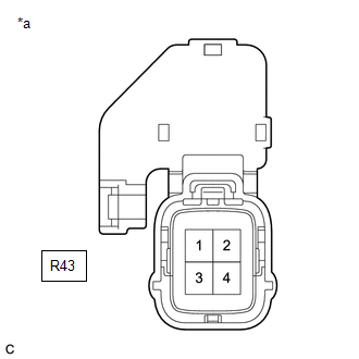
|
*a | Front view of wire harness connector (to Fuel Pump (for low pressure side)) |
(a) Disconnect the fuel pump (for low pressure side) connector.
(b) Connect the Techstream to the DLC3.
(c) Turn the engine switch on (IG).
(d) Turn the Techstream on.
(e) Enter the following menus: Powertrain / Engine / Active Test / Fuel Pump Single Phase Energization.
Powertrain > Engine > Active Test|
Tester Display |
|---|
| Fuel Pump Single Phase Energization |
(f) Operate the fuel pump control ECU using the Active Test function and measure the voltage according to the value(s) in the table below.
Standard Voltage:
|
Tester Connection | GTS Operation |
Specified Condition |
|---|---|---|
|
R43-3 (BLPU) - Body ground |
U Phase | 4.4 to 8.4 V* |
|
R43-4 (BLPV) - Body ground |
V Phase | 4.4 to 8.4 V* |
|
R43-2 (BLPW) - Body ground |
W Phase | 4.4 to 8.4 V* |
HINT:
- *: This Active Test restricts the fuel pump control ECU output duty cycle to 50%. Therefore, the output voltage of the fuel pump control ECU will be approximately 50% of the power source voltage.
- Before performing this inspection, check that the battery voltage is between 11 and 14 V (not depleted).
- Perform "Inspection After Repair" after replacing the fuel pump (for low pressure side).
Click here
| OK | | REPLACE FUEL PUMP (FOR LOW PRESSURE SIDE)
|
|
| 9. |
CHECK HARNESS AND CONNECTOR (FUEL PUMP CONTROL ECU - FUEL PUMP (FOR LOW PRESSURE SIDE)) |
(a) Disconnect the fuel pump control ECU connector.
(b) Disconnect the fuel pump (for low pressure side) connector.
(c) Measure the resistance according to the value(s) in the table below.
Standard Resistance:
|
Tester Connection | Condition |
Specified Condition |
|---|---|---|
|
R17-2 (FPU) - R43-3 (BLPU) |
Always | Below 1 Ω |
|
R17-3 (FPV) - R43-4 (BLPV) |
Always | Below 1 Ω |
|
R17-4 (FPW) - R43-2 (BLPW) |
Always | Below 1 Ω |
|
R17-2 (FPU) or R43-3 (BLPU) - Body ground and other terminals |
Always | 10 kΩ or higher |
|
R17-3 (FPV) or R43-4 (BLPV) - Body ground and other terminals |
Always | 10 kΩ or higher |
|
R17-4 (FPW) or R43-2 (BLPW) - Body ground and other terminals |
Always | 10 kΩ or higher |
| NG | | REPAIR OR REPLACE HARNESS OR CONNECTOR |
|
| 10. |
CHECK HARNESS AND CONNECTOR (POWER SOURCE OF FUEL PUMP CONTROL ECU) |
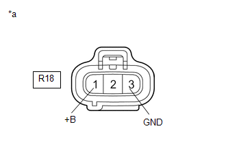
|
*a | Front view of wire harness connector (to Fuel Pump Control ECU) |
(a) Disconnect the fuel pump control ECU connector.
(b) Turn the engine switch on (IG).
(c) Measure the voltage according to the value(s) in the table below.
Standard Voltage:
|
Tester Connection | Condition |
Specified Condition |
|---|---|---|
|
R18-1 (+B) - R18-3 (GND) |
Engine switch on (IG) |
11 to 14 V |
HINT:
Make a note of the measured voltage as it may be used in a following Active Test.
| NG | | GO TO STEP 13 |
|
| 11. |
INSPECT ECM (FPC TERMINAL) |
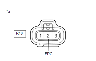
|
*a | Front view of wire harness connector (to Fuel Pump Control ECU) |
(a) Disconnect the fuel pump control ECU connector.
(b) Connect the Techstream to the DLC3.
(c) Turn the engine switch on (IG).
(d) Turn the Techstream on.
(e) Enter the following menus: Powertrain / Engine / Active Test / Fuel Pump Single Phase Energization.
Powertrain > Engine > Active Test|
Tester Display |
|---|
| Fuel Pump Single Phase Energization |
(f) Operate the fuel pump control ECU using the Active Test function and measure the resistance according to the value(s) in the table below.
Standard Resistance:
|
Tester Connection | Techstream Operation |
Specified Condition |
|---|---|---|
|
R18-2 (FPC) - Body ground |
Before Active Test → During Active Test |
Before Active Test: Resistance is stable → During Active Test: Resistance fluctuates* |
HINT:
*: Using the Active Test, duty control of the transistors in the ECM will be performed. Due to the duty control, resistance of the FPC terminal will be unstable during the Active Test. If the resistance is stable before the Active Test and fluctuates while performing the Active Test, it can be determined that the transistor is operating. If the transistor does not operate during the Active Test, the ECM may be malfunctioning.
| OK | | REPLACE FUEL PUMP CONTROL ECU
|
|
| 12. |
CHECK HARNESS AND CONNECTOR (FUEL PUMP CONTROL ECU - ECM) |
(a) Disconnect the fuel pump control ECU connector.
(b) Disconnect the ECM connector.
(c) Measure the resistance according to the value(s) in the table below.
Standard Resistance:
|
Tester Connection | Condition |
Specified Condition |
|---|---|---|
|
R18-2 (FPC) - A21-18 (FPC) |
Always | Below 1 Ω |
|
R18-2 (FPC) or A21-18 (FPC) - Body ground and other terminals |
Always | 10 kΩ or higher |
| OK | | REPLACE ECM
|
| NG | | REPAIR OR REPLACE HARNESS OR CONNECTOR |
| 13. |
CHECK HARNESS AND CONNECTOR (FUEL PUMP CONTROL ECU - BODY GROUND) |
(a) Disconnect the fuel pump control ECU connector.
(b) Measure the resistance according to the value(s) in the table below.
Standard Resistance:
|
Tester Connection | Condition |
Specified Condition |
|---|---|---|
|
R18-3 (GND) - Body ground |
Always | Below 1 Ω |
| NG | | REPAIR OR REPLACE HARNESS OR CONNECTOR |
|
| 14. |
CHECK HARNESS AND CONNECTOR (POWER SOURCE VOLTAGE OF EFI-MAIN NO. 2 RELAY) |
(a) Remove the EFI-MAIN NO. 2 relay from the No. 1 engine room relay block and No. 1 junction block assembly.
(b) Measure the voltage according to the value(s) in the table below.
Standard Voltage:
|
Tester Connection | Condition |
Specified Condition |
|---|---|---|
|
3 (EFI-MAIN NO. 2 relay) - Body ground |
Always | 11 to 14 V |
| NG | | REPAIR OR REPLACE HARNESS OR CONNECTOR (BATTERY - EFI-MAIN NO. 2 RELAY) |
|
| 15. |
INSPECT EFI-MAIN NO. 2 RELAY |
(a) Inspect the EFI-MAIN NO. 2 relay.
Click here
| NG | | REPLACE EFI-MAIN NO. 2 RELAY |
|
| 16. |
CHECK HARNESS AND CONNECTOR (EFI-MAIN NO. 1 RELAY - ECM) |
(a) Remove the EFI-MAIN NO. 1 relay from the No. 1 engine room relay block and No. 1 junction block assembly.
(b) Disconnect the ECM connector.
(c) Measure the resistance according to the value(s) in the table below.
Standard Resistance:
|
Tester Connection | Condition |
Specified Condition |
|---|---|---|
|
2 (EFI-MAIN NO. 1 relay) - A21-46 (MREL) |
Always | Below 1 Ω |
|
2 (EFI-MAIN NO. 1 relay) or A21-46 (MREL) - Body ground and other terminals |
Always | 10 kΩ or higher |
| NG | | REPAIR OR REPLACE HARNESS OR CONNECTOR |
|
| 17. |
CHECK HARNESS AND CONNECTOR (EFI-MAIN NO. 1 RELAY - EFI-MAIN NO. 2 RELAY) |
(a) Remove the EFI-MAIN NO. 1 and EFI-MAIN NO. 2 relays from the No. 1 engine room relay block and No. 1 junction block assembly.
(b) Measure the resistance according to the value(s) in the table below.
Standard Resistance:
|
Tester Connection | Condition |
Specified Condition |
|---|---|---|
|
5 (EFI-MAIN NO. 1 relay) - 2 (EFI-MAIN NO. 2 relay) |
Always | Below 1 Ω |
|
5 (EFI-MAIN NO. 1 relay) or 2 (EFI-MAIN NO. 2 relay) - Body ground and other terminals |
Always | 10 kΩ or higher |
| NG | | REPAIR OR REPLACE HARNESS OR CONNECTOR |
|
| 18. |
CHECK HARNESS AND CONNECTOR (EFI-MAIN NO. 2 RELAY - BODY GROUND) |
(a) Remove the EFI-MAIN NO. 2 relay from the No. 1 engine room relay block and No. 1 junction block assembly.
(b) Measure the resistance according to the value(s) in the table below.
Standard Resistance:
|
Tester Connection | Condition |
Specified Condition |
|---|---|---|
|
1 (EFI-MAIN NO. 2 relay) - Body ground |
Always | Below 1 Ω |
| NG | | REPAIR OR REPLACE HARNESS OR CONNECTOR |
|
| 19. |
CHECK HARNESS AND CONNECTOR (EFI-MAIN NO. 2 RELAY - FUEL PUMP CONTROL ECU) |
(a) Remove the EFI-MAIN NO. 2 relay from the No. 1 engine room relay block and No. 1 junction block assembly.
(b) Disconnect the fuel pump control ECU connector.
(c) Measure the resistance according to the value(s) in the table below.
Standard Resistance:
|
Tester Connection | Condition |
Specified Condition |
|---|---|---|
|
5 (EFI-MAIN NO. 2 relay) - R18-1 (+B) |
Always | Below 1 Ω |
|
5 (EFI-MAIN NO. 2 relay) or R18-1 (+B) - Body ground and other terminals |
Always | 10 kΩ or higher |
| OK | | GO TO ECM POWER SOURCE CIRCUIT |
| NG | | REPAIR OR REPLACE HARNESS OR CONNECTOR |
READ NEXT:
 Starter Signal Circuit
DESCRIPTION While the engine is being cranked, current flows from terminal STAR of the certification ECU (smart key ECU assembly) to the park/neutral position switch assembly and to terminal STA of th
ACIS Control Circuit
DESCRIPTION ACIS (Acoustic Control Induction System) controls the opening and closing the intake air control valve sub-assembly built into the intake air surge tank assembly to increase the intake eff
Brake Override System
DESCRIPTION When the vehicle is being driven, depressing the accelerator pedal sensor assembly and brake pedal will activate the brake override system to restrict engine output. The conditions for act
SEE MORE:
GVIF Disconnected (from Extension Module to H/U) (B153A)
DESCRIPTION
DTC No. Detection Item
DTC Detection Condition Trouble Area
B153A GVIF Disconnected (from Extension Module to H/U)
GVIF disconnected (from navigation ECU to radio and display receiver assembly)
No. 1 navigation wire
Navigation ECU
Rad
Components
COMPONENTS ILLUSTRATION
*1 FRONT FENDER APRON SEAL LH
*2 FRONT FENDER APRON SEAL RH
*3 FRONT WHEEL OPENING EXTENSION PAD LH
*4 FRONT WHEEL OPENING EXTENSION PAD RH
*5 NO. 1 ENGINE UNDER COVER
*6 NO. 2 ENGINE UNDER COVER ASSEMBLY
