Toyota Camry (XV70): GVIF Disconnected (from Extension Module to H/U) (B153A)
DESCRIPTION
|
DTC No. | Detection Item |
DTC Detection Condition | Trouble Area |
|---|---|---|---|
|
B153A | GVIF Disconnected (from Extension Module to H/U) |
GVIF disconnected (from navigation ECU to radio and display receiver assembly) |
|
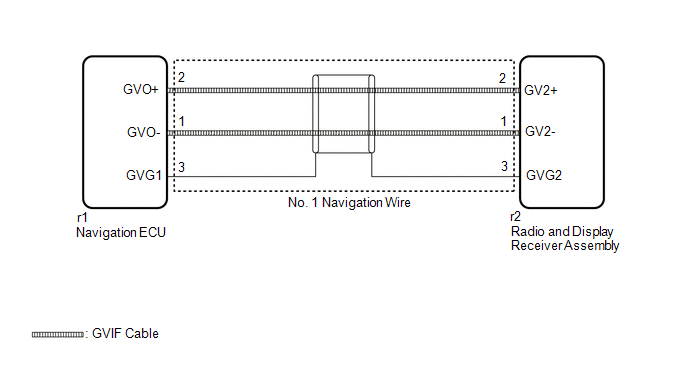
WIRING DIAGRAM
CAUTION / NOTICE / HINT
NOTICE:
- Depending on the parts that are replaced during vehicle inspection or maintenance, performing initialization, registration or calibration may be needed. Refer to Precaution for Navigation System.
Click here
.gif)
- When replacing the radio and display receiver assembly or navigation ECU, always replace it with a new one. If a radio and display receiver assembly or navigation ECU which was installed to another vehicle is used, the following may occur:
- A communication malfunction DTC may be stored.
- The radio and display receiver assembly or navigation ECU may not operate normally.
PROCEDURE
|
1. | CHECK DTC |
(a) Clear the DTCs.
Body Electrical > Navigation System > Clear DTCs(b) Recheck for DTCs and check that no DTCs are output.
Body Electrical > Navigation System > Trouble CodesOK:
No DTCs are output.
| OK | .gif) |
USE SIMULATION METHOD TO CHECK |
|
.gif)
| 2. |
CHECK NO. 1 NAVIGATION WIRE (RADIO AND DISPLAY RECEIVER ASSEMBLY - NAVIGATION ECU) |
| (a) Disconnect the r1 navigation ECU connector. |
|
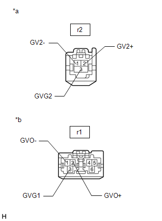
(b) Disconnect the r2 radio and display receiver assembly connector.
(c) Measure the resistance according to the value(s) in the table below.
Standard Resistance:
|
Tester Connection | Condition |
Specified Condition |
|---|---|---|
|
r1-1 (GVO-) - r2-1 (GV2-) |
Always | Below 1 Ω |
|
r1-2 (GVO+) - r2-2 (GV2+) |
Always | Below 1 Ω |
|
r1-3 (GVG1) - r2-3 (GVG2) |
Always | Below 1 Ω |
| NG | | REPLACE NO. 1 NAVIGATION WIRE
|
|
| 3. |
REPLACE NAVIGATION ECU |
(a) Replace the Navigation ECU with a new one.
Click here
|
| 4. |
CHECK DTC |
(a) Clear the DTCs.
Body Electrical > Navigation System > Clear DTCs(b) Recheck for DTCs and check that no DTCs are output.
Body Electrical > Navigation System > Trouble CodesOK:
No DTCs are output.
| OK | |
END (NAVIGATION ECU IS DEFECTIVE) |
| NG | | REPLACE RADIO AND DISPLAY RECEIVER ASSEMBLY
|
READ NEXT:
 Extension Module Disconnected 2 (B1543)
DESCRIPTION If the radio and display receiver assembly cannot detect the navigation ECU for a certain period of time (90 seconds) after the engine switch is turned on (ACC) and the radio and display r
HD Radio Tuner Malfunction (B1551,B158D,B15A0,B15B0,B15B3,B15B7,B15BA,B15F9)
DESCRIPTION These DTCs are stored when a malfunction occurs in the radio and display receiver assembly.
DTC No. Detection Item
DTC Detection Condition Trouble Area
B1551 HD Ra
Extension Module Malfunction 2 (B1556)
DESCRIPTION These DTCs are stored when a malfunction occurs in the Navigation ECU.
DTC No. Detection Item
DTC Detection Condition Trouble Area
B1556 Extension Module Malfuncti
SEE MORE:
Components
COMPONENTS ILLUSTRATION
*1 NO. 2 PARKING BRAKE WIRE ASSEMBLY
*2 REAR DISC BRAKE ANTI-SQUEAL SHIM KIT
*3 REAR DISC BRAKE PAD
*4 REAR DISC BRAKE CYLINDER ASSEMBLY
*5 REAR NO. 1 DISC BRAKE ANTI-SQUEAL SHIM
*6 REAR NO. 2 DISC BRAKE ANTI-SQUEAL SHIM
Installation
INSTALLATION PROCEDURE 1. INSTALL LEAK DETECTION PUMP SUB-ASSEMBLY
HINT: Only perform this procedure when replacement of the leak detection pump sub-assembly is necessary.
(a) Engage the 2 claws to install a new leak detection pump sub-assembly to the No. 2 charcoal canister sub-assembly.
