Toyota Camry (XV70): Extension Module Disconnected 2 (B1543)
DESCRIPTION
If the radio and display receiver assembly cannot detect the navigation ECU for a certain period of time (90 seconds) after the engine switch is turned on (ACC) and the radio and display receiver assembly confirms that the information is missing by checking past navigation ECU recognition information (registered information), this DTC will be stored.
HINT:
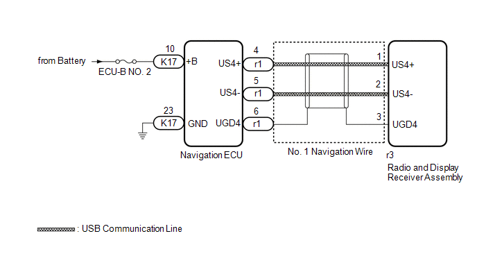
The Navigation system uses USB communication between devices. If an open, short, short to +B or short to ground occurs in the USB circuit, communication is interrupted and the Navigation system will not operate normally.
|
DTC No. | Detection Item |
DTC Detection Condition | Trouble Area |
|---|---|---|---|
|
B1543 | Extension Module Disconnected 2 |
Navigation ECU disconnected |
|
HINT:
This DTC may be stored due to environmental reasons such as electrical noise or interference.
WIRING DIAGRAM
CAUTION / NOTICE / HINT
NOTICE:
- Depending on the parts that are replaced during vehicle inspection or maintenance, performing initialization, registration or calibration may be needed. Refer to Precaution for Navigation System.
Click here
.gif)
- Inspect the fuses for circuits related to this system before performing the following procedure.
- When replacing the radio and display receiver assembly or navigation ECU, always replace it with a new one. If a radio and display receiver assembly or navigation ECU which was installed to another vehicle is used, the following may occur:
- A communication malfunction DTC may be stored.
- The radio and display receiver assembly or navigation ECU may not operate normally.
PROCEDURE
|
1. | CHECK MAP SCREEN |
(a) Turn the engine switch on (ACC) and wait for 90 seconds.
(b) Press the "MAP" switch and check that the map screen is displayed normally.
|
Result | Proceed to |
|---|---|
|
Map screen is displayed normally |
A |
| Map screen is not displayed normally |
B |
HINT:
- This DTC may be stored due to environmental reasons such as electrical noise or interference.
- Clear past DTCs when the map screen is displayed normally. (Codes stored due to past environmental factors)
| A | .gif) | USE SIMULATION METHOD TO CHECK
|
|
.gif)
| 2. |
CHECK DTC |
(a) Clear the DTCs.
Body Electrical > Navigation System > Clear DTCs(b) Turn the engine switch off.
(c) Turn the engine switch on (IG) and wait for 90 seconds.
(d) Recheck for DTCs and check that no DTCs are output.
Body Electrical > Navigation System > Trouble CodesOK:
No DTCs are output.
| OK | |
USE SIMULATION METHOD TO CHECK |
|
| 3. |
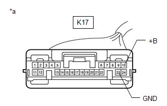
CHECK HARNESS AND CONNECTOR (NAVIGATION ECU - BATTERY AND BODY GROUND) |
| (a) Disconnect the navigation ECU connector. |
|
(b) Measure the resistance according to the value(s) in the table below.
Standard Resistance:
|
Tester Connection | Condition |
Specified Condition |
|---|---|---|
|
K17-23 (GND) - Body ground |
Always | Below 1 Ω |
(c) Measure the voltage according to the value(s) in the table below.
Standard Voltage:
|
Tester Connection | Condition |
Specified Condition |
|---|---|---|
|
K17-10 (+B) - Body ground |
Always | 11 to 14 V |
| NG | | REPAIR OR REPLACE HARNESS OR CONNECTOR |
|
| 4. |
CHECK NO. 1 NAVIGATION WIRE (RADIO AND DISPLAY RECEIVER ASSEMBLY - NAVIGATION ECU) |
| (a) Disconnect the r1 navigation ECU connector. |
|
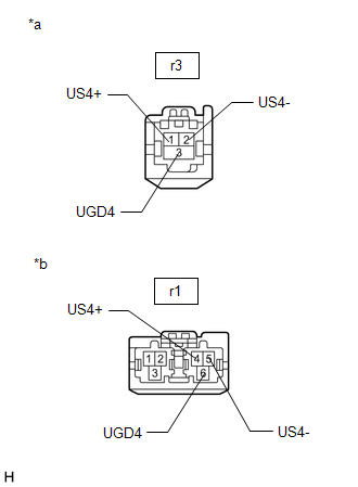
(b) Disconnect the r3 radio and display receiver assembly connector.
(c) Measure the resistance according to the value(s) in the table below.
Standard Resistance:
|
Tester Connection | Condition |
Specified Condition |
|---|---|---|
|
r1-4 (US4+) - r3-1 (US4+) |
Always | Below 1 Ω |
|
r1-5 (US4-) - r3-2 (US4-) |
Always | Below 1 Ω |
|
r1-6 (UGD4) - r3-3 (UGD4) |
Always | Below 1 Ω |
| NG | | REPLACE NO. 1 NAVIGATION WIRE
|
|
| 5. |
REPLACE NAVIGATION ECU |
(a) Replace the navigation ECU with a new one.
Click here
|
| 6. |
CHECK DTC |
(a) Clear the DTCs.
Body Electrical > Navigation System > Clear DTCs(b) Turn the engine switch off.
(c) Turn the engine switch on (IG) and wait for 90 seconds.
(d) Recheck for DTCs and check that no DTCs are output.
Body Electrical > Navigation System > Trouble CodesOK:
No DTCs are output.
| OK | |
END (NAVIGATION ECU IS DEFECTIVE) |
| NG | | REPLACE RADIO AND DISPLAY RECEIVER ASSEMBLY
|
READ NEXT:
 HD Radio Tuner Malfunction (B1551,B158D,B15A0,B15B0,B15B3,B15B7,B15BA,B15F9)
DESCRIPTION These DTCs are stored when a malfunction occurs in the radio and display receiver assembly.
DTC No. Detection Item
DTC Detection Condition Trouble Area
B1551 HD Ra
Extension Module Malfunction 2 (B1556)
DESCRIPTION These DTCs are stored when a malfunction occurs in the Navigation ECU.
DTC No. Detection Item
DTC Detection Condition Trouble Area
B1556 Extension Module Malfuncti
Voice Recognition Microphone Disconnected (B1579)
DESCRIPTION The radio and display receiver assembly, roof console box sub-assembly and telephone microphone assembly are connected to each other using the microphone connection detection signal lines.
SEE MORE:
Installation
INSTALLATION PROCEDURE 1. INSTALL FUEL PRESSURE SENSOR (FUEL DELIVERY PIPE WITH SENSOR ASSEMBLY)
HINT: Perform "Inspection After Repair" after replacing the fuel pressure sensor (fuel delivery pipe with sensor assembly).
Click here
Click here
NOTICE:
Do not remove the fuel pressu
Components
COMPONENTS ILLUSTRATION
*1 FRONT FENDER APRON SEAL RH
*2 V-BANK COVER SUB-ASSEMBLY
N*m (kgf*cm, ft.*lbf): Specified torque
- - ILLUSTRATION
*1 CAMSHAFT TIMING OIL CONTROL SOLENOID ASSEMBLY (for Intake Side of Bank 1)
*2 CAMSHAFT TIMIN
