Toyota Camry (XV70): Components
COMPONENTS
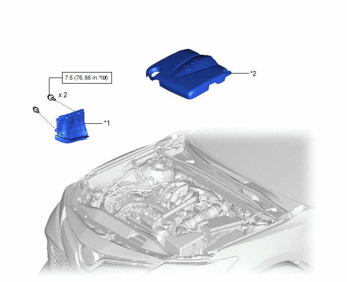
ILLUSTRATION
|
*1 | FRONT FENDER APRON SEAL RH |
*2 | V-BANK COVER SUB-ASSEMBLY |
.png) |
N*m (kgf*cm, ft.*lbf): Specified torque |
- | - |
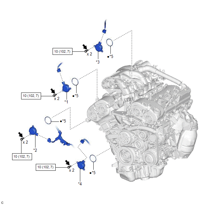
ILLUSTRATION
|
*1 | CAMSHAFT TIMING OIL CONTROL SOLENOID ASSEMBLY (for Intake Side of Bank 1) |
*2 | CAMSHAFT TIMING OIL CONTROL SOLENOID ASSEMBLY (for Exhaust Side of Bank 1) |
|
*3 | CAMSHAFT TIMING OIL CONTROL SOLENOID ASSEMBLY (for Intake Side of Bank 2) |
*4 | CAMSHAFT TIMING OIL CONTROL SOLENOID ASSEMBLY (for Exhaust Side of Bank 2) |
|
*5 | O-RING |
- | - |
|
|
N*m (kgf*cm, ft.*lbf): Specified torque |
● | Non-reusable part |
.png) |
Adhesive 1324 | ★ |
Precoated part |
READ NEXT:
 On-vehicle Inspection
ON-VEHICLE INSPECTION PROCEDURE
1. INSPECT CAMSHAFT TIMING OIL CONTROL SOLENOID ASSEMBLY (a) Connect the Techstream to the DLC3.
(b) Start the engine. (c) Turn the Techstream on. (d) Inspect the c
Removal
REMOVAL PROCEDURE 1. REMOVE V-BANK COVER SUB-ASSEMBLY
Click here
2. REMOVE CAMSHAFT TIMING OIL CONTROL SOLENOID ASSEMBLY (for Exhaust Side of Bank 2)
(a) Disconnect the camshaft ti
Inspection
INSPECTION PROCEDURE 1. INSPECT CAMSHAFT TIMING OIL CONTROL SOLENOID ASSEMBLY
HINT: Use the same procedure for the intake side and exhaust side.
(a) Check the resistance.
(1) Measure the res
SEE MORE:
Problem Symptoms Table
PROBLEM SYMPTOMS TABLE If DTCs are not output but the malfunction persists, use the following table to determine which circuits to inspect for each problem symptom.
HINT: Refer to each inspection procedure for related problem symptoms. Vehicle Stability Control System
Symptom Suspected Are
Brake Switch "A" Circuit Short to Battery (P057112)
DESCRIPTION The skid control ECU (brake actuator assembly) receives stop light switch assembly signals and uses them to determine whether or not the brakes are applied.
DTCs may be stored if either of the following occurs:
Stop light switch assembly stuck on malfunction.
The accelerator a
© 2023-2025 Copyright www.tocamry.com
