Toyota Camry (XV70): Inspection
INSPECTION
PROCEDURE
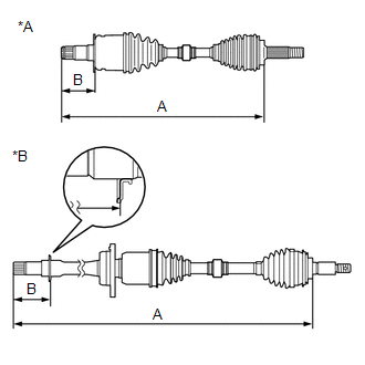
1. INSPECT FRONT DRIVE SHAFT ASSEMBLY
| (a) Check that there is no excessive play in the radial direction of the outboard joint. |
|
.png)
(b) Check that the inboard joint slides smoothly in the thrust direction.
(c) Check that there is no excessive play in the radial direction of the inboard joint.
(d) Check the boots for damage.
| (e) Check whether the drive shaft dimension (A) and (B) are within specification. NOTICE: Keep the drive shaft assembly level during inspection. Dimension (A):
Dimension (B):
|
| ||||||||||||||||||||||
READ NEXT:
 Reassembly
REASSEMBLY CAUTION / NOTICE / HINT
HINT:
Use the same procedure for the RH side and LH side.
The following procedure is for the LH side.
PROCEDURE 1. INSTALL FRONT DRIVE SHAFT BEARING (f
Installation
INSTALLATION CAUTION / NOTICE / HINT
HINT:
Use the same procedure for the RH side and LH side.
The following procedure is for the LH side.
PROCEDURE 1. INSTALL FRONT DRIVE SHAFT HOLE SNA
SEE MORE:
Shift Paddle Switch Circuit
DESCRIPTION Moving the shift lever to S enables the shift range to be selected. The shift range can be selected by operating the "+" or "-" shift paddle switch. WIRING DIAGRAM
CAUTION / NOTICE / HINT
NOTICE: After turning the engine switch off, waiting time may be required before disconnecting
Software Incompatibility with Body Control Module "B" (U1331)
DESCRIPTION This DTC is stored when the destination information of the main body ECU (multiplex network body ECU) does not match that of the blind spot monitor sensors. Blind Spot Monitor Master
DTC No. Detection Item
DTC Detection Condition Trouble Area
U1331 Software Incom
© 2023-2025 Copyright www.tocamry.com
