Toyota Camry (XV70): Inspection
INSPECTION
PROCEDURE
1. INSPECT WATER INLET WITH THERMOSTAT SUB-ASSEMBLY
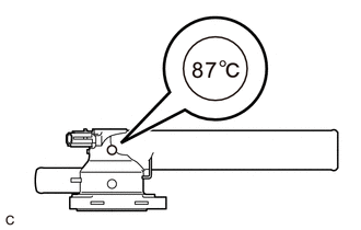
(a) Check the valve opening.
HINT:
The valve opening temperature is inscribed on the water inlet with thermostat sub-assembly.
| (1) Add 15 cc (0.9 cu. in.) of water to the water inlet with thermostat sub-assembly from the inlet pipe side. |
|
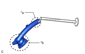
(2) Confirm that water does not flow out from the valve side of the water inlet with thermostat sub-assembly.
If water flows out from the valve side of the water inlet with thermostat sub-assembly, replace the water inlet with thermostat sub-assembly with a new one.
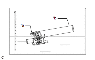
(3) Immerse the water inlet with thermostat sub-assembly in water that is between 92°C (198°F) and 96°C (205°F) for 5 minutes or more.
NOTICE:
- Do not allow any water to come into contact with the connector of the water inlet with thermostat sub-assembly.
- Make sure that the end of the inlet pipe of the water inlet with thermostat sub-assembly is not facing downward.
- Make sure to immerse the water inlet with thermostat sub-assembly in the water as shown in the illustration.
|
*a | Connector |
|
*b | Inlet Pipe |
 |
Temperature Sensor |
| (4) Leave the water inlet with thermostat sub-assembly at ambient temperature for 5 minutes so that the valve closes. NOTICE: Make sure that the end of the inlet pipe of the water inlet with thermostat sub-assembly is not facing downward. |
|
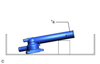
(5) Check that the water that was added to the water inlet with thermostat sub-assembly has completely flowed out.
If the water that was added to the water inlet with thermostat sub-assembly has not completely flowed out, replace the water inlet with thermostat sub-assembly with a new one.
(b) Check the resistance of the temperature sensor.
(1) Measure the resistance according to the value(s) in the table below.
Standard Resistance:
|
Tester Connection | Condition |
Specified Condition |
|---|---|---|
|
1 - 2 | Always |
10.6 to 14.2 Ω |
If the result is not as specified, replace the water inlet with thermostat sub-assembly.
READ NEXT:
 Installation
INSTALLATION PROCEDURE 1. INSTALL WATER INLET WITH THERMOSTAT SUB-ASSEMBLY
(a) Install a new gasket to the water inlet with thermostat sub-assembly.
(b) Install the water inlet with thermostat sub
Components
COMPONENTS ILLUSTRATION
*1 ENGINE WATER PUMP ASSEMBLY
*2 NO. 2 IDLER PULLEY SUB-ASSEMBLY
*3 WATER PUMP PULLEY
*4 WATER PUMP GASKET
*5 V-RIBBED BELT
SEE MORE:
Knock Sensor 1 Bank 1 or Single Sensor Circuit Short to Battery or Open (P032515,P033015)
DESCRIPTION Refer to DTC P032511. Click here
HINT: When DTC P032515 or P033015 is stored, the ECM enters fail-safe mode. During fail-safe mode, the ignition timing is delayed to its maximum retardation. Fail-safe mode continues until the engine switch is turned off.
DTC No. Detection Ite
Brake Switch "A" Circuit Short to Battery (P057112)
DESCRIPTION The skid control ECU (brake actuator assembly) receives stop light switch assembly signals and uses them to determine whether or not the brakes are applied.
DTCs may be stored if either of the following occurs:
Stop light switch assembly stuck on malfunction.
The accelerator a
