Toyota Camry (XV70): Installation
INSTALLATION
PROCEDURE
1. INSTALL WATER INLET WITH THERMOSTAT SUB-ASSEMBLY
(a) Install a new gasket to the water inlet with thermostat sub-assembly.
(b) Install the water inlet with thermostat sub-assembly with the 2 bolts and 2 nuts.
Torque:
10 N·m {102 kgf·cm, 7 ft·lbf}
2. CONNECT WATER BY-PASS HOSE
(a) Connect the water by-pass hose and slide the clip to secure it.
3. INSTALL FRONT NO. 1 ENGINE MOUNTING BRACKET LH
Click here .gif)
4. CONNECT ENGINE WIRE
(a) Engage the clamp to connect the engine wire.
(b) Install the bolt.
Torque:
10 N·m {102 kgf·cm, 7 ft·lbf}
(c) Connect the water inlet with thermostat sub-assembly connector.
5. INSTALL ENGINE MOUNTING INSULATOR SUB-ASSEMBLY RH
| (a) Install the engine mounting insulator sub-assembly RH to the engine mounting spacer and vehicle body with the nut and 2 bolts. Torque: 72 N·m {734 kgf·cm, 53 ft·lbf} NOTICE: Temporarily tighten the bolt (A), and then fully tighten the 2 bolts and nut in the order of (B), (A) and (C). |
|
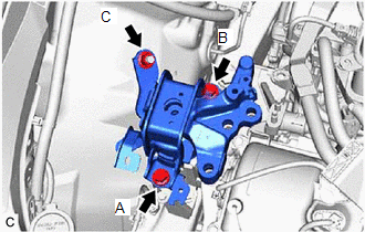
(b) Install the engine mounting insulator sub-assembly RH to the front No. 1 engine mounting bracket LH with the 3 bolts and nut.
Torque:
Bolt :
72 N·m {734 kgf·cm, 53 ft·lbf}
Nut :
42 N·m {428 kgf·cm, 31 ft·lbf}
(c) Install the suction hose sub-assembly, suction pipe sub-assembly and air conditioning tube and accessory assembly with the bolt.
Torque:
8.0 N·m {82 kgf·cm, 71 in·lbf}
(d) Engage the 2 clamps.
6. INSTALL RADIATOR RESERVE TANK ASSEMBLY
| (a) Install the radiator reserve tank assembly with the bolt and nut in the order shown in the illustration. Torque: 5.0 N·m {51 kgf·cm, 44 in·lbf} |
|
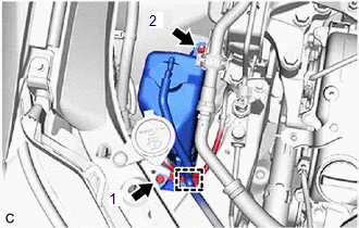
(b) Engage the clamp.
7. INSTALL ENGINE MOUNTING STAY NO.2 RH
Click here
8. INSTALL V-BANK COVER SUB-ASSEMBLY
Click here
9. ADD ENGINE COOLANT
Click here
10. INSPECT FOR COOLANT LEAK
Click here
11. INSTALL ENGINE UNDER COVER REAR RH
Click here
12. INSTALL ENGINE UNDER COVER REAR LH
Click here
13. INSTALL ENGINE UNDER COVER NO.1
Click here
14. INSTALL FRONT WHEEL OPENING EXTENSION PAD RH
Click here
15. INSTALL FRONT WHEEL OPENING EXTENSION PAD LH
Click here
READ NEXT:
 Components
COMPONENTS ILLUSTRATION
*1 ENGINE WATER PUMP ASSEMBLY
*2 NO. 2 IDLER PULLEY SUB-ASSEMBLY
*3 WATER PUMP PULLEY
*4 WATER PUMP GASKET
*5 V-RIBBED BELT
On-vehicle Inspection
ON-VEHICLE INSPECTION CAUTION / NOTICE / HINT
HINT:
Water Pump Construction Evaporation Port and Drain Plug:
*1
Evaporation Port
*2
Me
SEE MORE:
Vehicle Lift And Support Locations
VEHICLE LIFT AND SUPPORT LOCATIONS NOTICE ABOUT VEHICLE CONDITION WHEN RAISING VEHICLE
(a) The vehicle must be unloaded before jacking up or raising the vehicle. Never jack up or raise a heavily loaded vehicle.
(b) When removing any heavy components like the engine or transmission, the vehicle c
Components
COMPONENTS ILLUSTRATION
*1 NO. 1 METER HOOD CLUSTER
*2 NO. 2 INSTRUMENT PANEL GARNISH SUB-ASSEMBLY
*3 INSTRUMENT PANEL FINISH PLATE GARNISH
*4 LOWER CENTER INSTRUMENT PANEL FINISH PANEL
*5 SHIFT LOCK RELEASE BUTTON COVER
*6 SHIFT LEVER KNOB SUB
