Toyota Camry (XV70): Inspection
INSPECTION
PROCEDURE
1. INSPECT VACUUM SWITCHING VALVE (for Active Control Engine Mount System)
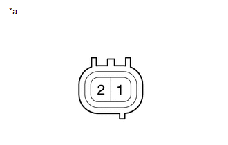
(a) Measure the resistance.
| (1) Measure the resistance according to the value(s) in the table below. Standard Resistance:
If the result is not as specified, replace the vacuum switching valve (for active control engine mount system). |
|
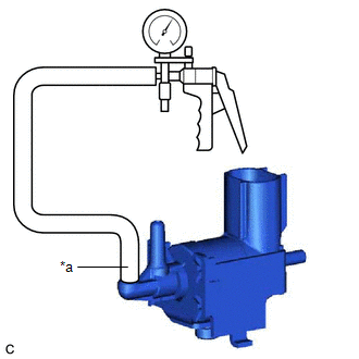
(b) Check the operation of the vacuum switching valve (for active control engine mount system).
| (1) Using a vacuum pump, apply a vacuum of 67 kPa (503 mmHg, 19.8 in. Hg) to port (F) and check that the vacuum is maintained. OK: Vacuum pressure holds. If the result is not as specified, replace the vacuum switching valve (for active control engine mount system). |
|
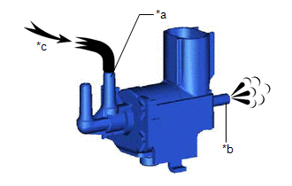
| (2) Check that air flows from port (E) to port (G). Standard: Air flows from port (E) to port (G). If the result is not as specified, replace the vacuum switching valve (for active control engine mount system). |
|
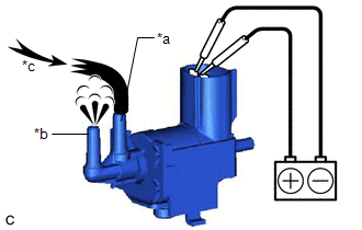
| (3) Apply battery voltage to the terminals and check that air flows from port (E) to port (F). Standard: Air flows from port (E) to port (F). If the result is not as specified, replace the vacuum switching valve (for active control engine mount system). |
|
READ NEXT:
 Installation
INSTALLATION PROCEDURE 1. INSTALL VACUUM SWITCHING VALVE (for Active Control Engine Mount System)
(a) Install the vacuum switching valve (for active control engine mount system) to the front engine
SEE MORE:
Clearance Warning Buzzer
ComponentsCOMPONENTS ILLUSTRATION
*A for 7 Inch Display
*B for 9 Inch Display
*1 CENTER INSTRUMENT CLUSTER FINISH PANEL ASSEMBLY
*2 CENTER INSTRUMENT CLUSTER FINISH PANEL SUB-ASSEMBLY
*3 LOWER INSTRUMENT PANEL FINISH PANEL ASSEMBLY
*4 NO. 1 CLE
ABS Pump Motor Control Internal Electronic Failure (C052C49)
DESCRIPTION The ABS motor relay and pump motor are built into the brake actuator assembly.
If the skid control ECU (brake actuator assembly) detects a malfunction in the drive circuit of the pump motor, this DTC is stored.
DTC No. Detection Item
DTC Detection Condition Trouble Area
