Toyota Camry (XV70): Clearance Warning Buzzer
Components
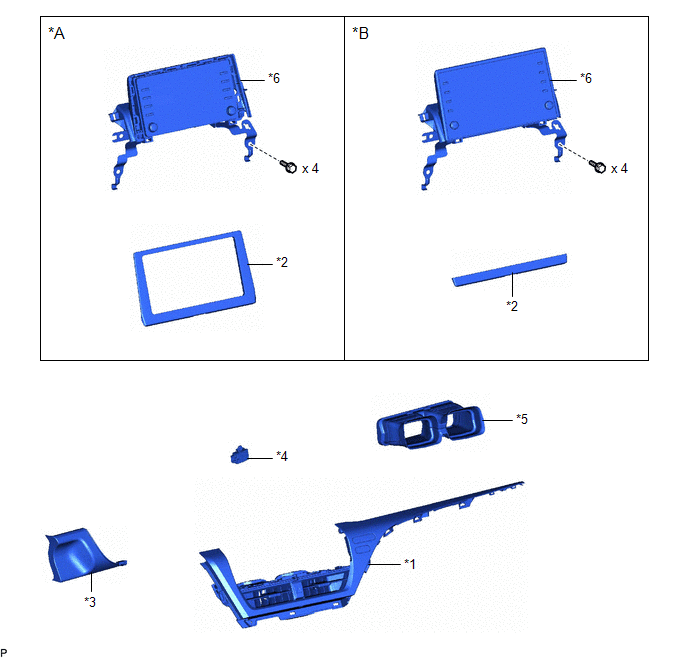
COMPONENTS
ILLUSTRATION
|
*A | for 7 Inch Display |
*B | for 9 Inch Display |
|
*1 | CENTER INSTRUMENT CLUSTER FINISH PANEL ASSEMBLY |
*2 | CENTER INSTRUMENT CLUSTER FINISH PANEL SUB-ASSEMBLY |
|
*3 | LOWER INSTRUMENT PANEL FINISH PANEL ASSEMBLY |
*4 | NO. 1 CLEARANCE WARNING BUZZER |
|
*5 | NO. 2 HEATER TO REGISTER DUCT SUB-ASSEMBLY |
*6 | RADIO AND DISPLAY RECEIVER ASSEMBLY WITH BRACKET |
Removal
REMOVAL
PROCEDURE
1. REMOVE AIR CONDITIONING CONTROL ASSEMBLY
Click here
.gif)
2. REMOVE LOWER INSTRUMENT PANEL FINISH PANEL ASSEMBLY
Click here
3. REMOVE CENTER INSTRUMENT CLUSTER FINISH PANEL SUB-ASSEMBLY (for 7 Inch Display)
Click here
4. REMOVE CENTER INSTRUMENT CLUSTER FINISH PANEL SUB-ASSEMBLY (for 9 Inch Display)
Click here
5. REMOVE CENTER INSTRUMENT CLUSTER FINISH PANEL ASSEMBLY
Click here
6. REMOVE RADIO AND DISPLAY RECEIVER ASSEMBLY WITH BRACKET (for 7 Inch Display)
Click here
7. REMOVE RADIO AND DISPLAY RECEIVER ASSEMBLY WITH BRACKET (for 9 Inch Display)
Click here
8. REMOVE NO. 2 HEATER TO REGISTER DUCT SUB-ASSEMBLY
Click here
9. REMOVE NO. 1 CLEARANCE WARNING BUZZER
| (a) Disengage the clamp. |
|
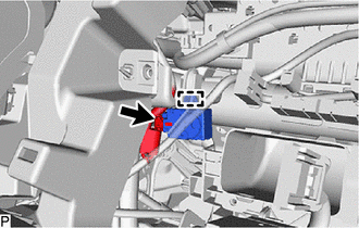
(b) Disconnect the connector to remove the No. 1 clearance warning buzzer.
Installation
INSTALLATION
PROCEDURE
1. INSTALL NO. 1 CLEARANCE WARNING BUZZER
(a) Connect the connector.
(b) Engage the clamp to install the No. 1 clearance warning buzzer.
2. INSTALL NO. 2 HEATER TO REGISTER DUCT SUB-ASSEMBLY
Click here .gif)
3. INSTALL RADIO AND DISPLAY RECEIVER ASSEMBLY WITH BRACKET (for 7 Inch Display)
Click here
4. INSTALL RADIO AND DISPLAY RECEIVER ASSEMBLY WITH BRACKET (for 9 Inch Display)
Click here
5. INSTALL CENTER INSTRUMENT CLUSTER FINISH PANEL ASSEMBLY
Click here
6. INSTALL CENTER INSTRUMENT CLUSTER FINISH PANEL SUB-ASSEMBLY (for 7 Inch Display)
Click here
7. INSTALL CENTER INSTRUMENT CLUSTER FINISH PANEL SUB-ASSEMBLY (for 9 Inch Display)
Click here
8. INSTALL LOWER INSTRUMENT PANEL FINISH PANEL ASSEMBLY
Click here
9. INSTALL AIR CONDITIONING CONTROL ASSEMBLY
Click here
READ NEXT:
 Components
COMPONENTS ILLUSTRATION
*1 CLEARANCE WARNING ECU ASSEMBLY
*2 ECU INTEGRATION BOX RH
*3 LOWER INSTRUMENT PANEL SUB-ASSEMBLY
- -
N*m (kgf*cm, ft.*lbf
Removal
REMOVAL CAUTION / NOTICE / HINT
The necessary procedures (adjustment, calibration, initialization, or registration) that must be performed after parts are removed and installed, or replaced during c
SEE MORE:
VSC does not Operate or VSC does not Operate Correctly
DESCRIPTION When TRAC or VSC is operating, the skid control ECU (brake actuator assembly) blinks the slip indicator light to inform the driver that slippage occurred.
When a communication malfunction with the ECM is detected, TRAC and VSC are disabled. Also, TRAC and VSC are disabled when a DTC is
Installation
INSTALLATION PROCEDURE 1. INSTALL CAMSHAFT TIMING GEAR BOLT
(a) Make sure that the No. 1 cylinder is at TDC/compression. HINT:
Check that the cutout of the camshaft timing gear assembly is at the top and align the timing mark (cutout) of the crankshaft pulley with the timing mark on the timing c
