Toyota Camry (XV70): Inspection
INSPECTION
PROCEDURE
1. INSPECT FUEL SENDER GAUGE ASSEMBLY
CAUTION:
Perform the inspection in a well-ventilated area.
Do not perform the inspection near an open flame.
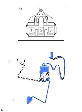
(a) Check that the float moves smoothly between F and E.
(b) Check the fuel sender gauge assembly voltage.
| (1) Apply 5 V between terminals 2 and 3. NOTICE:
HINT: If a stable power supply is not available, connect 4 nickel-metal hydride batteries (1.2 V each) or equivalent in series. |
|
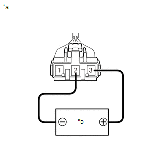
| (2) Measure the voltage according to the value(s) in the table below. Standard Voltage:
*: The output voltage changes depending on the voltage applied to the terminals. Output voltage (F) = (0.851 x Voltage applied to terminals) to (0.921 x Voltage applied to terminals) Output voltage (E) = (0.069 x Voltage applied to terminals) to (0.139 x Voltage applied to terminals) If the result is not as specified, replace the fuel sender gauge assembly. |
|
READ NEXT:
 Installation
INSTALLATION PROCEDURE 1. INSTALL FUEL SENDER GAUGE ASSEMBLY
(a) Engage the claw to install the fuel sender gauge assembly to the fuel suction tube with pump and gauge assembly.
NOTICE: Be careful
Components
COMPONENTS ILLUSTRATION
*1 FUEL SENDER GAUGE ASSEMBLY
*2 FUEL SUCTION TUBE WITH PUMP AND GAUGE ASSEMBLY
Removal
REMOVAL CAUTION / NOTICE / HINT
The necessary procedures (adjustment, calibration, initialization or registration) that must be performed after parts are removed and installed, or replaced during fu
SEE MORE:
Inspection
INSPECTION PROCEDURE 1. INSPECT AND ADJUST BRAKE BOOSTER PUSH ROD
NOTICE: Make the adjustment with no vacuum in the brake booster assembly. (Depress the brake pedal several times with the engine stopped.)
HINT:
Adjustment of the brake booster push rod is required when the brake master cylind
Check For Intermittent Problems
CHECK FOR INTERMITTENT PROBLEMS CHECK FOR INTERMITTENT PROBLEMS
HINT: A momentary interruption (open circuit) in the connectors and/or wire harness between the sensors and ECUs can be detected using the Data List function of the Techstream.
(a) Turn the ignition switch off. (b) Connect the Techs
