Toyota Camry (XV70): Installation
INSTALLATION
CAUTION / NOTICE / HINT
NOTICE:
- Immediately after installing the front disc brake pads, the braking performance may be reduced. Always perform a road test in a safe place while paying attention to the surroundings.
- After replacing the front disc brake pads, the brake pedal may feel soft due to clearance between the front disc brake pads and front disc. Depress the brake pedal several times until the brake pedal feels firm.
- After replacing the front disc brake pads, always perform a road test to check the braking performance and check for vibrations.
HINT:
- Use the same procedure for the RH side and LH side.
- The following procedure is for the LH side.
PROCEDURE
1. INSTALL FRONT DISC BRAKE ANTI-SQUEAL SHIM KIT
NOTICE:
- When replacing worn front disc brake pads, the front disc brake anti-squeal shims and front disc brake pad wear indicator plates must be replaced together with the front disc brake pads.
- Do not apply lubricants to the lining surface of the brake pad.
- Install the front disc brake pad wear indicator plates in the correct position and direction.
- Install the front disc brake anti-squeal shims in the correct position and direction.
| (a) Install the front No. 1 disc brake anti-squeal shim and front No. 2 disc brake anti-squeal shim to each front disc brake pad. |
|
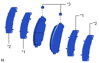
(b) Install the front disc brake pad wear indicator plate to each front disc brake pad.
2. INSTALL FRONT DISC BRAKE PAD
CAUTION:
- Be careful not to get pinched by the front disc brake cylinder assembly or other parts when installing the front disc brake pads.
- After lifting up the front disc brake cylinder assembly, secure it in place before performing any work on it.
- The front disc brake cylinder assembly could fall, pinching hands or fingers and causing injury.
.png)
(a) Push in the front disc brake pistons.
NOTICE:
- Make sure that the brake fluid does not overflow from the reservoir.
- Do not forcibly push in the front disc brake pistons.
(b) Install the 2 front disc brake pads to the front disc brake cylinder mounting.
NOTICE:
- Keep the friction surfaces of the front disc brake pads and front disc free from oil and grease.
- Install the front disc brake pad so that the pad wear indicator plate is mounted on the upper side of the vehicle.
(c) Install the 2 anti-squeal springs to the front disc brake pads.
NOTICE:
- When replacing the front disc brake pads with new ones, make sure to replace the anti-squeal springs at the same time.
- Be sure to install the anti-squeal springs into the front disc brake pad installation holes as far as they will go.
(d) Hold the front disc brake cylinder slide pin (lower side) and install the front disc brake cylinder assembly to the front disc brake cylinder mounting with the bolt.
Torque:
34.3 N
READ NEXT:
 Front Side Marker Light Bulb
ComponentsCOMPONENTS ILLUSTRATION
*1 FRONT SIDE MARKER LIGHT BULB
- - RemovalREMOVAL CAUTION / NOTICE / HINT
HINT:
Use the same procedure for the RH side and LH side.
Front Turn Signal Light Bulb
ComponentsCOMPONENTS ILLUSTRATION
*1 FRONT TURN SIGNAL LIGHT BULB
- - RemovalREMOVAL CAUTION / NOTICE / HINT
HINT:
Use the same procedure for the RH side and LH side.
Front Wiper Rubber
ComponentsCOMPONENTS ILLUSTRATION
*1 FRONT WIPER BLADE
*2 WIPER RUBBER
*3 FRONT WIPER RUBBER BACKING PLATE
- - RemovalREMOVAL CAUTION / NOTICE / HINT
NOTICE:
SEE MORE:
Pressure Control Solenoid "G" Circuit Short to Ground or Open (P280714)
DESCRIPTION Refer to DTC P280712. Click here
DTC No. Detection Item
DTC Detection Condition Trouble Area
MIL Memory
Note P280714
Pressure Control Solenoid "G" Circuit Short to Ground or Open
While the vehicle is being driven so that gear changes occur,
Satellite Radio Broadcast cannot be Selected or After Selecting Broadcast, Broadcast cannot be Added into Memory
CAUTION / NOTICE / HINT NOTICE: Some satellite radio broadcasts require payment. A contract must be made between a satellite radio company and the user. If the contract expires, it will not be possible to listen to the broadcast. PROCEDURE
1.
CHECK SATELLITE RADIO (a) Check radio condi
