Toyota Camry (XV70): Installation
INSTALLATION
PROCEDURE
1. PRECAUTION (w/o Navigation System)
NOTICE:
- When replacing the radio and display receiver assembly, always replace it with a new one. If a radio and display receiver assembly which was installed to another vehicle is used, the following may occurs:
- A communication malfunction DTC may be stored.
- The radio and display receiver assembly may not operate normally.
NOTICE:
Click here .gif)
2. PRECAUTION (w/ Navigation System)
NOTICE:
- When replacing the radio and display receiver assembly or navigation ECU, always replace it with a new one. If a radio and display receiver assembly or navigation ECU which was installed to another vehicle is used, the following may occur:
- A communication malfunction DTC may be stored.
- The radio and display receiver assembly or navigation ECU may not operate normally.
- After replacing the radio and display receiver assembly, if "New software is not compatible with the system. Contact your dealer." is displayed on the multi-display, update the software of the navigation ECU.
NOTICE:
Click here
3. INSTALL RADIO AND DISPLAY RECEIVER ASSEMBLY
4. INSTALL NO. 1 RADIO RECEIVER BRACKET
(a) Install the No. 1 radio receiver bracket with the 2 screws.
5. INSTALL NO. 2 RADIO RECEIVER BRACKET
(a) Install the No. 2 radio receiver bracket with the 2 screws.
6. INSTALL CENTER INSTRUMENT CLUSTER FINISH UPPER PANEL ASSEMBLY (for 7 Inch Display)
(a) Engage the 3 clips to install the center instrument cluster finish upper panel assembly as shown in the illustration.
.png) |
Install in this Direction |
7. INSTALL RADIO AND DISPLAY RECEIVER ASSEMBLY WITH BRACKET (for 7 Inch Display)
(a) Connect each connector.
(b) Engage the 2 guides to temporarily install the radio and display receiver assembly with bracket as shown in the illustration.
|
|
Install in this Direction |
(c) Engage the 2 clips and 2 claws as shown in the illustration.
|
|
Install in this Direction |
(d) Install the radio and display receiver assembly with bracket with the 4 bolts.
(e) Engage the clamp.
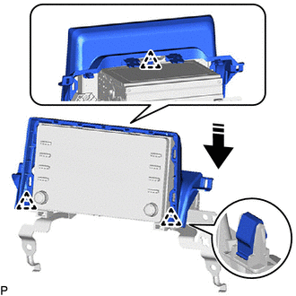
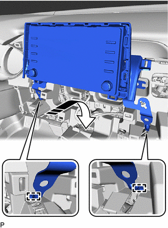
8. INSTALL RADIO AND DISPLAY RECEIVER ASSEMBLY WITH BRACKET (for 9 Inch Display)
(a) Connect each connector.
(b) Engage the 2 guides to temporarily install the radio and display receiver assembly with bracket as shown in the illustration.
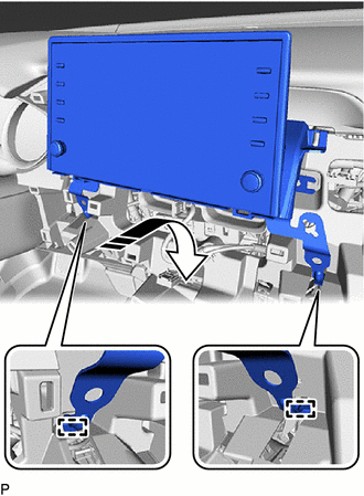
|
|
Install in this Direction |
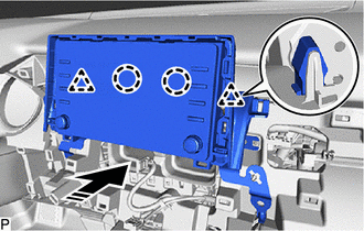
(c) Engage the 5 clips as shown in the illustration.
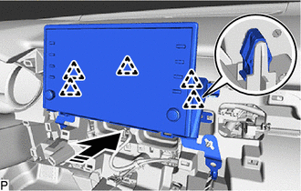
|
|
Install in this Direction |
(d) Install the radio and display receiver assembly with bracket with the 4 bolts.
(e) Engage the clamp.
9. INSTALL CENTER INSTRUMENT CLUSTER FINISH PANEL ASSEMBLY
Click here
10. INSTALL CENTER INSTRUMENT CLUSTER FINISH PANEL SUB-ASSEMBLY (for 7 Inch Display)
Click here
11. INSTALL CENTER INSTRUMENT CLUSTER FINISH PANEL SUB-ASSEMBLY (for 9 Inch Display)
Click here
12. INSTALL LOWER INSTRUMENT PANEL FINISH PANEL ASSEMBLY
Click here
13. INSTALL AIR CONDITIONING CONTROL ASSEMBLY
Click here
READ NEXT:
 Components
COMPONENTS ILLUSTRATION
*1 REAR ARMREST ASSEMBLY
*2 REAR DOOR ARMREST COVER SUB-ASSEMBLY
*3 REAR DOOR INNER GLASS WEATHERSTRIP
*4 REAR DOOR NO. 2 SERVICE HOLE COV
Removal
REMOVAL CAUTION / NOTICE / HINT
HINT:
Use the same procedure for the RH side and LH side.
The following procedure is for the LH side.
PROCEDURE 1. REMOVE REAR DOOR ARMREST COVER SUB-ASSE
SEE MORE:
Rear seats (folding type)
The seatbacks of the rear seats can be folded down.
Folding down the rear seatbacks
Pull the seatback lever in the trunk
for the seatback you wish to fold
down and then fold the seatback
down.
WARNING
■When folding the seatbacks down
Observe the following precautions. Failure to do so
Inspection
INSPECTION PROCEDURE 1. INSPECT CAMSHAFT TIMING GEAR BOLT
(a) Check the stroke of the plunger in the center of the camshaft timing gear bolt.
Standard Stroke: 4.5 mm (0.177 in.) or more HINT: When pressing the plunger, there may be a stepped feeling. This is not a malfunction.
If the re
