Toyota Camry (XV70): Installation
INSTALLATION
CAUTION / NOTICE / HINT
HINT:
- Use the same procedure for the RH side and LH side.
- The following procedure is for the LH side.
PROCEDURE
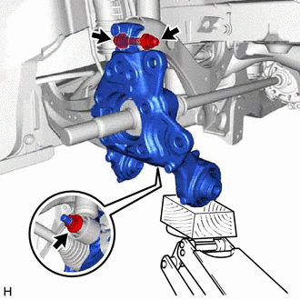
1. TEMPORARILY INSTALL REAR AXLE CARRIER SUB-ASSEMBLY
| (a) Temporarily install the rear axle carrier sub-assembly to the rear shock absorber assembly with the nut and plate washer. NOTICE: Hold the rear axle carrier pin while rotating the nut. |
|
(b) Temporarily install the rear axle carrier sub-assembly to the rear upper control arm assembly with the bolt and nut.
NOTICE:
- Insert the bolt with the threaded end facing the rear of the vehicle.
- Because the nut has its own stopper, do not turn the nut. Tighten the bolt with the nut secured.
| (c) Install the rear trailing arm assembly to the rear axle carrier sub-assembly with the 3 bolts and nut. Torque: Bolt A : 135 N |
READ NEXT:
 Components
COMPONENTS ILLUSTRATION
*1 NO. 2 PARKING BRAKE WIRE ASSEMBLY
*2 REAR AXLE HUB AND BEARING ASSEMBLY
*3 REAR DISC
*4 REAR DISC BRAKE CALIPER ASSEMBLY
*5 R
On-vehicle Inspection
ON-VEHICLE INSPECTION CAUTION / NOTICE / HINT
HINT:
Use the same procedure for the RH side and LH side.
The following procedure is for the LH side.
PROCEDURE 1. REMOVE REAR WHEEL Click h
SEE MORE:
Terminals Of Ecu
TERMINALS OF ECU CHECK 4WD ECU ASSEMBLY
(a) Measure the voltage and resistance of the connector.
Terminal No. (Symbol) Wiring Color
Terminal Description Condition
Specified Condition
K145-6 (CANH) - K145-5 (CANL)
P - W HIGH-level CAN bus wire - LOW-level CAN bu
Stereo Jack Adapter Assembly
ComponentsCOMPONENTS ILLUSTRATION
*1 LOWER CENTER INSTRUMENT PANEL FINISH PANEL
*2 NO. 1 METER HOOD CLUSTER
*3 NO. 1 STEREO JACK ADAPTER ASSEMBLY
- - RemovalREMOVAL PROCEDURE
1. REMOVE NO. 1 METER HOOD CLUSTER Click here
2. REMOVE LOWER CENTER IN
© 2023-2025 Copyright www.tocamry.com
