Toyota Camry (XV70): Installation
INSTALLATION
PROCEDURE
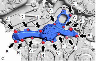
1. INSTALL ENGINE WATER PUMP ASSEMBLY
| (a) Install a new water pump gasket and the engine water pump assembly with the 15 bolts. Torque: Bolt (A) : 43 N·m {438 kgf·cm, 32 ft·lbf} Bolt (B) : 21 N·m {214 kgf·cm, 15 ft·lbf} Bolt (C) : 11 N·m {112 kgf·cm, 8 ft·lbf} Standard Length:
NOTICE:
|
|
2. INSTALL WATER PUMP PULLEY
(a) Temporarily install the water pump pulley with the 4 bolts.
| (b) Using a screwdriver or equivalent with its tip wrapped in protective tape, hold the water pump pulley. |
|
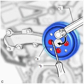
(c) Fully tighten the 4 bolts.
Torque:
21 N·m {214 kgf·cm, 15 ft·lbf}
3. INSTALL NO. 2 IDLER PULLEY SUB-ASSEMBLY
(a) Install the No. 2 idler pulley sub-assembly with the bolt.
Torque:
54 N·m {551 kgf·cm, 40 ft·lbf}
4. INSTALL V-RIBBED BELT
Click here .gif)
5. INSTALL WATER INLET WITH THERMOSTAT SUB-ASSEMBLY
Click here
READ NEXT:
 Components
COMPONENTS ILLUSTRATION
*1 FRONT FLOOR COVER LH
*2 FRONT FLOOR COVER RH
N*m (kgf*cm, ft.*lbf): Specified torque
- - ILLUSTRATION
*1 CENTER FL
SEE MORE:
Stereo Component Amplifier Malfunction (B15A3)
DESCRIPTION This DTC is stored when a malfunction occurs in the stereo component amplifier assembly.
DTC No. Detection Item
DTC Detection Condition Trouble Area
B15A3 Stereo Component Amplifier Malfunction
When any of the following conditions is met:
Internal
RR Speed Sensor Wrong Installation (X0454)
DESCRIPTION
Code Tester Display
Measurement Item Trouble Area
X0454 RR Speed Sensor Wrong Installation
History of rear speed sensor RH being installed incorrectly
Rear Speed Sensor RH PROCEDURE
1.
CHECK FOR DTCs (HEALTH CHECK) (a) Perform the Hea
