Toyota Camry (XV70): Installation
INSTALLATION
PROCEDURE
1. INSTALL AIR FUEL RATIO SENSOR (for Bank 1)
HINT:
Perform "Inspection After Repair" after replacing the air fuel ratio sensor.
Click here .gif)
| (a) Using SST, install the air fuel ratio sensor to the exhaust manifold assembly RH (TWC: Front Catalyst). SST: 09224-00012 Torque: Specified tightening torque : 44 N·m {449 kgf·cm, 32 ft·lbf} NOTICE: If the air fuel ratio sensor has been struck or dropped, replace it. HINT:
|
|
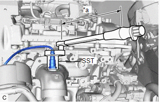
(b) Engage the 2 wire harness clamps.
(c) Connect the air fuel ratio sensor connector.
2. INSTALL AIR FUEL RATIO SENSOR (for Bank 2)
HINT:
Perform "Inspection After Repair" after replacing the air fuel ratio sensor.
Click here
| (a) Using SST, install the air fuel ratio sensor to the exhaust manifold assembly LH (TWC: Front Catalyst). SST: 09224-00012 Torque: Specified tightening torque : 44 N·m {449 kgf·cm, 32 ft·lbf} NOTICE: If the air fuel ratio sensor has been struck or dropped, replace it. HINT:
|
|
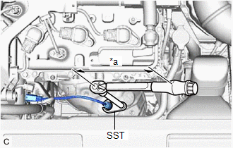
(b) Connect the air fuel ratio sensor connector.
(c) Engage the wire harness clamp.
3. INSTALL V-BANK COVER SUB-ASSEMBLY
Click here
4. INSPECT FOR EXHAUST GAS LEAK
Click here
5. PERFORM INITIALIZATION
(a) Perform "Inspection After Repair" after replacing an air fuel ratio sensor.
Click here
READ NEXT:
 Components
COMPONENTS ILLUSTRATION
*1 FRONT FENDER APRON SEAL RH
*2 V-BANK COVER SUB-ASSEMBLY
N*m (kgf*cm, ft.*lbf): Specified torque
- - ILLUSTRATION
*1
On-vehicle Inspection
ON-VEHICLE INSPECTION PROCEDURE
1. INSPECT CAMSHAFT TIMING OIL CONTROL SOLENOID ASSEMBLY (a) Connect the Techstream to the DLC3.
(b) Start the engine. (c) Turn the Techstream on. (d) Inspect the c
SEE MORE:
How To Proceed With Troubleshooting
CAUTION / NOTICE / HINT
HINT:
The ECM is connected to the CAN communication system. Therefore, before starting troubleshooting, make sure to check that there are no malfunctions in the CAN communication system.
*: Use the Techstream.
PROCEDURE
1. VEHICLE BROUGHT TO WORKSHOP
Internal Control Module EEPROM Data Memory Failure (P062F44)
DESCRIPTION The ECM monitors its internal operation and stores this DTC when it detects an internal malfunction.
DTC No. Detection Item
DTC Detection Condition Trouble Area
MIL Memory
Note P062F44
Internal Control Module EEPROM Data Memory Failure
An ECM in
